background image

2-6

S

UPER

S

ERVER 6037R-TXRF User's Manual

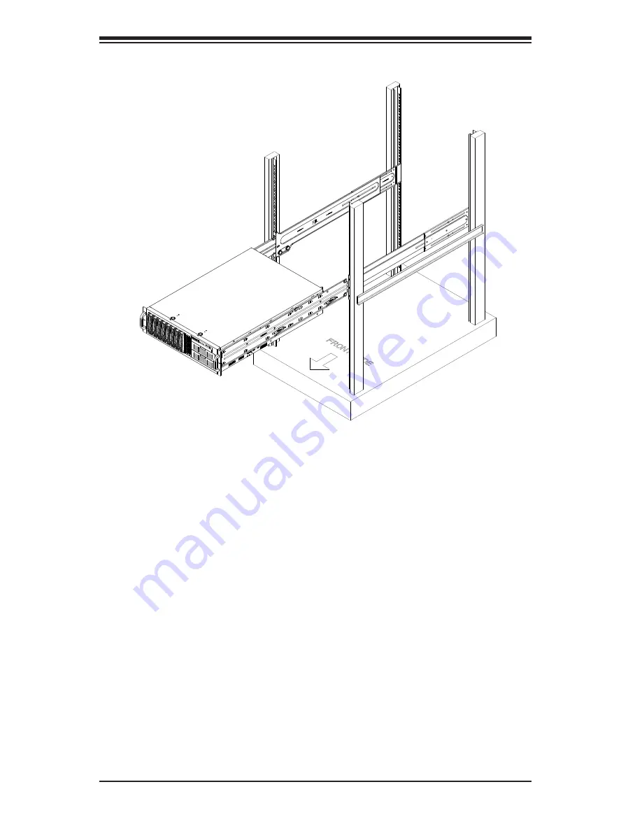
Figure 2-4.  Installing the Chassis into the Rack

Installing the Chassis into a Rack

Installing into a Rack

1. 

Confirm that the inner and outer rails are installed on the rack. 

2.  Line chassis rails with the front of the rack rails.

3.  Slide the chassis rails into the rack rails, keeping the pressure even on both 

sides (you may have to depress the locking tabs when inserting). When the 
server has been pushed completely into the rack, you should hear the locking 
tabs "click" into position. 

4.  (Optional) Insert and tighten the thumbscrews that hold the front of the server 

to the rack.

Summary of Contents for SUPERSERVER 6037R-TXRF

Page 1: ...SUPERSERVER 6037R TXRF SUPER USER S MANUAL Revision 1 0...

Page 2: ...f any such disputes Super Micro s total liability for all claims will not exceed the price paid for the hardware product FCC Statement This equipment has been tested and found to comply with the limit...

Page 3: ...tallation This chapter describes the steps necessary to install the system into a rack and check out the server configuration prior to powering up the system If your server was ordered without the pro...

Page 4: ...SC835XTQ R982B server chassis You should follow the procedures given in this chapter when installing removing or reconfiguring SATA or peripheral drives and when replacing system power supply units a...

Page 5: ...v Preface Notes...

Page 6: ...iew 2 1 2 2 Unpacking the System 2 1 2 3 Preparing for Setup 2 1 Choosing a Setup Location 2 1 Rack Precautions 2 2 Server Precautions 2 2 Rack Mounting Considerations 2 3 Ambient Operating Temperatur...

Page 7: ...npacking 5 2 5 2 Connecting Cables 5 2 Connecting Data Cables 5 2 Connecting Power Cables 5 2 Connecting the Control Panel 5 2 5 3 I O Ports 5 3 5 4 Installing the Processor and Heatsink 5 4 Installin...

Page 8: ...ard Drive Backplane 6 6 SATA Drive Installation 6 6 DVD ROM Drive Installation 6 9 6 5 Power Supply 6 10 Power Supply Failure 6 10 Replacing the Power Supply 6 10 Chapter 7 BIOS 7 1 Introduction 7 1 S...

Page 9: ...the system www supermicro com In addition to the serverboard and chassis various hardware components have been included with the server as listed below One 8 cm rear exhaust fan FAN 0125L4 Three 8 cm...

Page 10: ...etails Serial ATA A SATA controller is integrated into the chipset to provide a ten port SATA subsystem which is RAID 0 1 5 and 10 supported I SATA 0 1 are SATA 3 0 ports and I SATA2 5 and S SATA0 3 a...

Page 11: ...ht SATA drives These drives are hot swappable units and are connected to a backplane that provides power and control Front Control Panel The control panel on the SuperServer 6037R TXRF provides you wi...

Page 12: ...R3 DIMM PROCESSOR SSB Socket 1 CPU FRONT PE3 P1 P0 PE2 PE1 DMI DMI PCI Windbond VGA VGA CONN DDR2 RAM TPM Header BMC PHY Super I O HW Monitor NCT7904D W83527 IPMI LAN RJ45 RTL8201F USB 10 11 LPC S SAT...

Page 13: ...per Micro Computer B V Het Sterrenbeeld 28 5215 ML s Hertogenbosch The Netherlands Tel 31 0 73 6400390 Fax 31 0 73 6416525 Email sales supermicro nl General Information support supermicro nl Technical...

Page 14: ...1 6 SUPERSERVER 6037R TXRF User s Manual Notes...

Page 15: ...itable location for the rack unit that will hold the SuperServer 6037R TXRF It should be situated in a clean dust free area that is well ventilated Avoid areas where heat electrical noise and electrom...

Page 16: ...r Always make sure the rack is stable before extending a component from the rack You should extend only one component at a time extending two or more si multaneously may cause the rack to become unsta...

Page 17: ...omised Mechanical Loading Equipment should be mounted into a rack so that a hazardous condition does not arise due to uneven mechanical loading Circuit Overloading Consideration should be given to the...

Page 18: ...ghtly You should also refer to the installation instructions that came with the rack unit you are using Installing the Inner Rack Rails Installing the Inner Rails 1 Place the inner rack extensions on...

Page 19: ...nt rail to the rear rail of the rack 2 Attach a short bracket to the front side of the right outer rail and a long bracket to the rear side of the right outer rail 3 Adjust both the short and long bra...

Page 20: ...he rack 2 Line chassis rails with the front of the rack rails 3 Slide the chassis rails into the rack rails keeping the pressure even on both sides you may have to depress the locking tabs when insert...

Page 21: ...of specific components There are also two buttons on the chassis control panel 3 2 Control Panel Buttons The two buttons located on the front of the chassis include a reset button and a power on off b...

Page 22: ...be off when the system is operating normally NIC1 Indicates network activity on the LAN1 port when flashing NIC2 Indicates network activity on the LAN2 port when flashing Information LED This LED wil...

Page 23: ...system is operating 3 4 Drive Carrier LEDs Each drive carrier has two LEDs Green When illuminated the green LED on the drive carrier indicates drive activity A connection to the backplane enables this...

Page 24: ...SUPERSERVER 6037R TXRF User s Manual 3 4 Notes...

Page 25: ...down the system with the operating system The unit has more than one power supply cord Disconnect both power supply cords before servicing to avoid electrical shock When working around exposed electr...

Page 26: ...product may be connected to an IT power system In all cases make sure that the unit is also reliably connected to Earth ground Serverboard Battery CAUTION There is a danger of explosion if the onboard...

Page 27: ...PCBs come into contact with your clothing which may retain a charge even if you are wearing a wrist strap Handle a board by its edges only do not touch its components peripheral chips memory modules o...

Page 28: ...ctly followed Figure 4 1 Installing the Onboard Battery LITHIUM BATTERY BATTERY HOLDER BATTERY HOLDER LITHIUM BATTERY OR Please handle used batteries carefully Do not damage the battery in any way a d...

Page 29: ...o handle them very carefully see previous chapter To prevent the serverboard from bending keep one hand under the center of the board to support it when handling The following measures are generally s...

Page 30: ...ith their locations noted should be connected See the serverboard layout for connector locations SATA drive data cables I SATA0 SATA7 Control Panel cable JF1 Important Make sure the the cables do not...

Page 31: ...are color coded in conformance with the PC 99 specification See Figure 5 2 below for the colors and locations of the various I O ports 1 1 1 7 1 5 1 6 1 4 1 3 1 2 1 8 1 9 1 10 Figure 5 2 I O Ports Po...

Page 32: ...g re moving or changing any hardware components Make sure that you install the processor into the CPU socket before you install the CPU heatsink If you buy a CPU separately make sure that you use an I...

Page 33: ...remove the WARNING plastic cap from the socket 5 Use your thumb and index finger to hold the CPU by its edges Align the CPU keys which are semi circle cutouts against the socket keys 6 Once they are a...

Page 34: ...e check that the CPU is aligned properly 7 With the CPU in the socket inspect the four corners of the CPU to make sure that they are flush with the socket 8 Close the load plate Lock the lever labeled...

Page 35: ...r the heatsink However if you do need to uninstall the heatsink please follow these instructions to avoid damaging the CPU or the CPU socket Installation and Removal of the Heatsink Uninstalling the H...

Page 36: ...e 5 3 3 Gently press down on the DIMM module until it snaps into place in the slot Repeat for all modules CAUTION Exercise extreme care when installing or removing DIMM modules to prevent any possible...

Page 37: ...guration Table For memory to work proper please install DIMMs in pairs 1 CPU 2 DIMMs CPU1 P1 DIMMA1 P1 DIMMB1 1 CPU 4 DIMMs CPU1 P1 DIMMA1 P1 DIMMB1 P1 DIMMC1 P1 DIMMD1 1 CPU 5 8 DIMMs CPU1 P1 DIMMA1...

Page 38: ...4Gb DRAMs are supported however only 2Gb and 4Gb DRAMs are validated 2 QR RDIMMs are supported but not validated Memory testing are limited to system level testing Signal integrity testing in in terop...

Page 39: ...TXRF server can support 10 PCI Express 3 0 x8 and one PCI Express 2 0 x4 in x8 slot expansion cards Installing an Add on Card 1 Locate the release tab on the top of the PCI slot bracket 2 Gently appl...

Page 40: ...0 x 8 CPU1 Slot 1 PCI E 3 0 x 8 USB8 9 USB6 7 CPU1 CPU2 P2 DIMMG1 P2 DIMMH2 P2 DIMMH1 P2 DIMMG2 P2 DIMME2 P2 DIMME1 P2 DIMMF2 P2 DIMMF1 P1 DIMMD1 P1 DIMMC2 P1 DIMMC1 P1 DIMMD2 P1 DIMMA1 P1 DIMMA2 P1 D...

Page 41: ...1 SATA 2 0 0 4 I SATA 2 5 Intel PCH SATA 2 0 Ports 2 5 Color Black JD1 Speaker Power LED Indicator JF1 Control Panel Header JIPMI1 4 pin External BMC I2 C Header for an IPMI Card JL1 Chassis Intrusio...

Page 42: ...Definition Pin Definition 13 3 3V 1 3 3V 14 12V 2 3 3V 15 COM 3 COM 16 PS_ON 4 5V 17 COM 5 COM 18 COM 6 5V 19 COM 7 COM 20 Res NC 8 PWR_OK 21 5V 9 5VSB 22 5V 10 12V 23 5V 11 12V 24 COM 12 3 3V Require...

Page 43: ...LED Connect an LED cable to pins 7 and 8 of Front Control Panel to use the Overheat Fan Fail Power Fail and UID LED connections The Red LED on pin 7 provides warnings of overheat fan failure or power...

Page 44: ...rt See the table on the right for pin definitions Serial COM Ports Pin Definitions Pin Definition Pin Definition 1 DCD 6 DSR 2 RXD 7 RTS 3 TXD 8 CTS 4 DTR 9 RI 5 Ground 10 N A Universal Serial Bus USB...

Page 45: ...next to the LAN ports on the backplane The Rear UID LED LED3 is located next to the UID Switch The Front Panel UID LED is located at Pins 7 8 of the Front Control Panel at JF1 Connect a cable to Pin 8...

Page 46: ...Thermal Management via Hardware Monitoring in the Advanced Setting in the BIOS for the 4 pin fans See Chapter 5 for more details In addition to 4 pin fans a 3 pin fan Fan PCH located next to the PCH...

Page 47: ...icator to provide warnings of chassis overheating and fan failure This LED will blink when a fan failure occurs Refer to the tables on right for pin definitions Overheat LED Pin Definitions Pin Defini...

Page 48: ...5 SATA Load 8 NC 7 SATA Clock Power LED Speaker On JD1 header pins 1 3 are used for power LED indication and pins 4 7 are for the speaker See the tables on the right for pin definitions Please note th...

Page 49: ...2 1 CMOS Clear JBT1 is used to clear CMOS which will also clear any passwords Instead of pins this jumper consists of contact pads to prevent accidentally clearing the contents of CMOS To clear CMOS 1...

Page 50: ...right for jumper settings Watch Dog must also be enabled in BIOS Note When enabled the user needs to write their own application software in order to disable the Watch Dog Timer Watch Dog Jumper Sett...

Page 51: ...ty Indicator LED Settings Color Status Definition Green Flashing Active Rear View when facing the rear side of the chassis Activity LED Link LED Activity LED Link LED Onboard Power LED An Onboard Powe...

Page 52: ...ear UID LED LED3 will be turned on Push the UID switch again to turn off the LED indicator The UID switch provides easy identification of a system unit that may be in need of service See the tables on...

Page 53: ...h your serverboard Figure 5 12 Driver Tool Installation Display Screen Note Click the icons showing a hand writing on paper to view the readme files for each item Click the computer icons to the right...

Page 54: ...ystem information such as CPU temperature system voltages and fan status See the Figure below for a display of the Supero Doctor III interface Note The default User Name and Password for SuperDoctor I...

Page 55: ...om our Web Site at ftp ftp supermicro com utility Supero_Doctor_III You can also download the SDIII User s Guide at http www supermicro com PRODUCT Manuals SDIII UserGuide pdf For Linux we will recomm...

Page 56: ...5 28 SUPERSERVER 6037R TXRF User s Manual Notes...

Page 57: ...m very carefully The following measures are generally sufficient to protect your equipment from ESD damage Precautions Use a grounded wrist strap designed to prevent static discharge Touch a grounded...

Page 58: ...ether to simplify the connection Connect the cable from JF1 on the serverboard to the Control Panel PCB printed circuit board Make sure the red wire plugs into pin 1 on both connectors Pull all excess...

Page 59: ...If the system has been installed to a rack carefully pull it out on the rails until the top cover is exposed 1 Press the release tabs to remove the cover from the locked position Press both tabs at t...

Page 60: ...h of the fans has failed Replacing System Fans Removing a Fan System power does not need to be removed since the fans are hot pluggable Replace the failed fan with an identical 8 cm 12 volt fan availa...

Page 61: ...Chapter 6 Advanced Chassis Setup 6 5 Figure 6 3 Replacing a Rear Fan Figure 6 4 Installing the Air Shroud...

Page 62: ...A DVD drive is included as an option only with the 6037R TXRF For installing removing the DVD ROM drive you will need to gain access to the inside of the server by removing the top cover of the chass...

Page 63: ...ce such as a desk table or work bench 4 Slide the hard drive into the tray with the printed circuit board side facing down 5 Carefully align the mounting holes in the hard drive and the tray Make sure...

Page 64: ...6 8 SUPERSERVER 6037R TXRF User s Manual Figure 6 5 Installing a Hard Drive to a Carrier Use a hard stable surface when installing the hard drive...

Page 65: ...are not installing a new front port panel remove the mini bezel from the drive bay The mini bezel is the small grating that covers the drive bay Remove this by simply pulling it out of the bay If you...

Page 66: ...thout powering down the system Replacing the Power Supply You do not need to shut down the system to replace a power supply unit The backup power supply module will keep the system up and running whil...

Page 67: ...ays all the options that can be configured Grayed out options cannot be configured Options in blue can be configured by the user The right frame displays the key legend Above the key legend is an area...

Page 68: ...rom the main menu you can access the other setup screens An AMI BIOS identification string is displayed at the left bottom corner of the screen below the copyright message Warning Do not upgrade the B...

Page 69: ...2 2011 System Time This item displays the system time in HH MM SS format e g 15 32 52 Supermicro X9DRX F Version This item displays the SMC version of the BIOS ROM used in this system Build Date This...

Page 70: ...ad of the normal POST messages The op tions are Enabled and Disabled AddOn ROM Display Mode Use this item to set the display mode for the Option ROM Select Keep Current to use the current AddOn ROM Di...

Page 71: ...f the system will power off immediately as soon as the user presses the power button If this feature is set to 4 Seconds Override the system will power off when the user presses the power button for 4...

Page 72: ...2 supports 64 bit technology Clock Spread Spectrum Select Enable to enable Clock Spectrum support which will allow the BIOS to moni tor and attempt to reduce the level of Electromagnetic Interference...

Page 73: ...security The options are Enabled and Disabled MLC Streamer Prefetcher Available when supported by the CPU If set to Enabled the MLC mid level cache streamer prefetcher will prefetch streams of data a...

Page 74: ...Efficiency and Custom If the option is set to Custom the following items will display EIST Available when Power Technology is set to Custom EIST Enhanced Intel SpeedStep Technology allows the system...

Page 75: ...ance Bias This setting allows the user to adjust the fan speed based on performance maxi mum cooling or energy efficiency maximum energy savings The options are Performance Balanced Performance Balanc...

Page 76: ...sharing The options are Enabled and Disabled Data Direct I O Select Enabled to enable Intel I OAT I O Acceleration Technology which sig nificantly reduces CPU overhead by leveraging CPU architectural...

Page 77: ...1 Gen2 and Gen3 IIO 2 PCIe Port Bifurcation Control This submenu configures the following IO PCIe Port Bifurcation Control settings for IIO 2 PCIe ports to determine how the available PCI Express lan...

Page 78: ...ules detected by the BIOS will be displayed as detected by the BIOS Memory Mode When Independent is selected all DIMMs are available to the operating system When Mirroring is selected the motherboard...

Page 79: ...ay The options are Enabled and Disabled Demand Scrub Demand Scrubbing is a process that allows the CPU to correct correctable memory errors found on a memory module When the CPU or I O issues a demand...

Page 80: ...st Controller Interface Controller 1 or Controller 2 The options are Disabled and Enabled Legacy USB Support Available when USB Functions is not Disabled Select Enabled to support legacy USB devices S...

Page 81: ...t the compatibility mode The options are Disabled Enhanced and Compatible The default for Controller 0 is Compatible The default of SATA Controller 1 is Enhanced AHCI Mode The following items are disp...

Page 82: ...and display the status of each SCU device as detected PCIe PCI PnP Configuration PCI ROM Priority Use this feature to select the Option ROM to boot the system when there are mul tiple Option ROMs avai...

Page 83: ...support The options are Disabled Force L0 and Auto Warning Enabling ASPM support may cause some PCI E devices to fail CPU1 PCIe Slot 1 x8 OPROM CPU1 PCIe Slot 2 x8 OPROM CPU1 PCIe Slot 3 x8 OPROM CPU1...

Page 84: ...em displays the Super IO chip used in the motherboard Serial Port 1 Configuration Serial Port Select Enabled to enable a serial port specified by the user The options are En abled and Disabled Device...

Page 85: ...onfigure the following Console Redirection settings for a COM Port specified by the user Console Redirection Select Enabled to use a COM Port selected by the user for Console Redirection The options a...

Page 86: ...sent along with the data bits Select Space to add a Space as a parity bit to be sent with your data bits The options are None Even Odd Mark and Space Stop Bits A stop bit indicates the end of a serial...

Page 87: ...computer will exchange data with the client computer which is the remote computer used by the user Out of Band Management Port The feature selects a serial port used by the Microsoft Windows Emergency...

Page 88: ...components such as RAMs to maintain the most critical functions of the system The options are S1 CPU_Stop_Clock and Suspend Disabled High Precision Event Timer Select Enabled to activate the High Pre...

Page 89: ...upport This feature indicates if the following hardware components support the Intel Trusted Execution Technology CPU TXT Trusted Execution Technology Feature Chipset TXT Trusted Execution Technology...

Page 90: ...the following information on the Intel I350 LAN connections NIC Configuration Link Speed Use this feature to change the link speed and duplex for the current port The op tions are AutoNeg 10Mbps Half...

Page 91: ...ing Disabling Options SMBIOS Event Log Select Enabled to enable SMBIOS System Management BIOS Event Logging during system boot The options are Enabled and Disabled Runtime Error Logging Support Select...

Page 92: ...d Settings Log System Boot Event Select Enabled to log system boot events The options are Disabled and Enabled MECI Multiple Event Count Increment Enter the increment value for the multiple event coun...

Page 93: ...in your system System Event Log Enabling Disabling Options SEL Components Select Enabled for all system event logging at bootup The options are Enabled and Disabled Erasing Settings Erase SEL Select Y...

Page 94: ...n is set to Yes the user is allow to configure the IPMI settings at next system boot Configuration Address Source This feature allows the user to select the source of the IP address for this com puter...

Page 95: ...iorities Boot Option 1 Boot Option 2 Boot Option 3 etc Use this feature to specify the sequence of boot device priority USB Device BBS Priorities Network Device BBS Priorities This option sets the ord...

Page 96: ...eature to set the Administrator Password which is required to enter the BIOS setup utility The length of the password should be from 3 characters to 8 characters long User Password Use this feature to...

Page 97: ...Reset When you have completed the system configuration changes select this option to save the changes and reboot the computer so that the new system configuration settings can take effect Select Save...

Page 98: ...ed defaults Save as User Defaults Select this feature and press Enter to save the current settings as the user s defaults When the dialog box appears asking you if you want to save values as user s de...

Page 99: ...possible repairs These fatal errors are usually communicated through a series of audible beeps The numbers on the fatal error list on the following page correspond to the number of beeps for the corre...

Page 100: ...A 2 SUPERSERVER 6037R TXRF User s Manual Notes...

Page 101: ...t can support up to 512 GB of DDR3 1333 1066 800 RDIMM LRDIMM or UDIMM ECC non ECC memory Note See the memory section in Chapter 5 for details SATA Controller Intel on chip controller for 10 SATA port...

Page 102: ...ating Temperature 40 to 60 C 40 to 140 F Operating Relative Humidity 8 to 95 non condensing Non operating Relative Humidity 5 to 95 non condensing Regulatory Compliance Electromagnetic Emissions FCC C...

Page 103: ...B 3 Appendix B System Specifications...

Page 104: ...rm be reasonably expected to result in significant injury or loss of life or catastrophic property damage Accordingly Supermicro dis claims any and all liability and should buyer use or sell such prod...

Reviews: