Chapter 5: Advanced Serverboard Setup
5-13
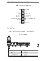
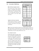
Power Button Connector
The PW_ON connector is on pins 1 and 2
of JF1. Momentarily contacting both pins
will power on/off the system. This button
can also be confi gured to function as a
suspend button (with a setting in the BIOS
- see Chapter 4). To turn off the power
when set to suspend mode, press the
button for at least 4 seconds. Refer to the
table on the right for pin defi nitions. This
header should be connected to the chassis
power button. See the table on the right for
pin defi nitions.
5-8 Connector
Defi nitions
Required Connection for GPUs
Power Button
Pin Defi nitions (JF1)
Pin# Defi nition
1
Power
2
Ground
Graphics Card Power Connectors
JPW2 and JPW3 must also be connected
to the power supply to provide power for
the GPUs. See the table on the right for
pin defi nitions.
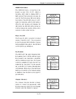
Main ATX Power Supply Connector
The primary power supply connector
(JPW1) is a proprietary design. Refer to
the table on the right for the pin defi nitions
of this connector. You must also connect
the 8-pin (JPW2/JPW3) graphics card
power connectors to your power supply
(see below).
20-pin Main Power Connector
Pin Defi nitions
Pin# Defi nition Pin # Defi nition
11
PS On
1
Ground
12
5VSB
2
Ground
13
Ground
3
Ground
14
Ground
4
Ground
15
Ground
5
Ground
16
NC2
6
NC1
17
12V
7
12V
18
12V
8
12V
19
12V
9
12V
20
12V
10
12V
Graphics Card Power Connector
Pin Defi nitions
Pin# Defi nition Pin # Defi nition
1
12V
5
Ground
2
12V
6
Ground
3
12V
7
Ground
4
Ground
8
Ground
Notes:
For the these proprietary connectors to work properly, please customize your
PWR cables based on the SMC PWR Connector Pin-Out Defi nitions listed in the
tables above. For the GPUs to work properly, connect the GPU power connectors
(JPW2/JPW3) to the power supply (6016GT series only).

