Chapter 1: Introduction
1-3
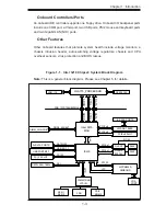
Figure 1-1 . Intel 3210 Chipset: System Block Diagram
Note:
This is a general block diagram. Please see Chapter 5 for details.
Intel 3210
LGA775_PROCESSOR
ICH9
WPCM450R
WINBOND
ADDR
CTRL
CTRL
ADDR
DATA
DATA
LPC
DDR2_800/667
DMI
DIMM_CHA/CHB
SATA/300
2x SATA PORTS
CK505 CLK
MCH
PCIE_x8
FSB: 1333/1066/800MHz
LPC
LSI SAS 1068E
8X SAS PORTS
PCIE_x1
GLAN1
USB PORTS 0-7
PCIE_x1
VRM 11.0
USB 2.0/1.1
SPI
SPI FLASH 16Mb
LPC I/O
SER.2
SER.1
FDD
KB/MS
PS/2
PCI_32
PCI_32 SLOT
PCI_32
W83627DHG
PCIE_x8
PCIE x8 SLOT
VGA
PORT
GLAN2
82574L
RJ45
RJ45
NC-SI
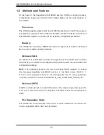
Onboard Controllers/Ports
An onboard IDE controller supports one fl oppy drive. Onboard I/O backpanel ports
include one COM port, a VGA port, two USB ports, PS/2 mouse and keyboard ports
and two Gigabit LAN (NIC) ports.
Other Features
Other onboard features that promote system health include voltage monitors, a
chassis intrusion header, auto-switching voltage regulators, chassis and CPU
overheat sensors, virus protection and BIOS rescue.
Summary of Contents for SUPERSERVER 5015B-M3
Page 1: ...SUPER USER S MANUAL Revision 1 0 SUPERSERVER 5015B M3...
Page 5: ...v Preface Notes...
Page 10: ...Notes SUPERSERVER 5015B M3 User s Manual x...
Page 16: ...1 6 SUPERSERVER 5015B M3 User s Manual Notes...
Page 30: ...3 4 SUPERSERVER 5015B M3 User s Manual Notes...
Page 60: ...5 26 SUPERSERVER 5015B M3 User s Manual Notes...
Page 68: ...6 8 SUPERSERVER 5015B M3 User s Manual Notes...

