background image

2-32


X9SAE Motherboard Series User’s Manual

10

9

2

1

BIOS LICENSE

1

3

JBT1

JSD1

1

3

JSTB

Y1

1

T-SGPIO1

1

2

7

8

T-SGPIO2

1

2

7

8

JTPM1

1

2

19

20

JPCIE

7

DIMM1

DIMM4

DIMM3

DIMM2

10

2

JPCI1

A1

B1

B2

JPCIE9

JUSBLAN2

JA

UDIO

1

J32

J15

2

1

7

J13

10

2

1

7

JD1

4

1

4

1

SP1

+

JWD1

JPL1

1

3

JPME2

1

3

JPME1

1

3

JPUSB1

13

JPUSB2

1

3

1

3

JCPUVRD_SMB

3

1

3

1

JPL2

3

1

R616

C

A

CA

TERR_LE

D

LED1

A

C

JPCIE6

B17

B18

A1

7

A1

8

JPCIE8

JPCIE5

J30

5

1

HDMI_

B1

+

C3102

JSPDIF_IN

JSPDIF_OUT

1

JL1

1

JI2C
2

1

JI2C
1

JUSB

4

11

10

19

1

B49

B48

A4

9

A4

8

Te

sted to 

Co

mply

W

ith FC

C Standards

FOR HOME OR OFFICE US

E

MAC C

ODE

BAR C

ODE

MH3

MH4

MH9

MH5

MH1

MH2

MH6

MH7

MH8

1-2:RST

2-3:NMI

JWD1

JPL1

:

2-3:DISABLE 1-2:ENABLE

2-3:ME MANU

FA

CT

URING MODE

1-2:NORMA

L

JP

ME1:

2-3:ME RE

CO
VE

RY

JP

ME2:

1-2:NORMA

L

JPW3

JPL2

1-2:Enabl

e

2-3:Disable

USB3.0 1/

2

1-2:Enabl

e

JPUSB1:USB1 

WA
KE UP

2-3:Disable

1-2:Enabl

e

JPUSB2:USB2 

WA
KE UP

2-3:Disable

JP

AC

1

PCH SL

OT

2 PCI-E 2.0 X4 (INX8)

CPU1 SL

OT

7 PCI-E 2.0 X4

FANA

USB2/3

CMOS CLEA

R

SPEAKER:1-4

JD1:

BUZZER:3-4

JL1:

CHASSIS INTRUSION

PWR RST

JF1

ON

LED

X

OH/FF

NIC2

NIC1

HDD PWR

LED

LED

BUZZER

POWER LED

JLED

FAN3

FAN2

FAN1/CPU FAN

AL

WA
YS

 POPUL

AT

E BL
UE SOCKE

T FIRS

T

AUDIO FP

JP

AC

1:A
UDIO

1-2:ENABLE

2-3:DISABLE

JPW2

JPW1

COM2

SL

OT

1 PCI 33MHZ

USB11/12

USB0/1

USB4/5

USB10/13

USB3.0 3/

4

COM1

VGA/

HDMI1/2

LAN2

LAN1

I-SATA0

I-SATA1

I-SATA2

I-SATA3

I-SATA4

I-SATA5

PCH SL

OT

3 PCI-E 2.0 X1

CPU1 SL

OT

4 PCI-E 3.0 X8 (INX16)

CPU1 SL

OT

6 PCI-E 3.0 X16

PCH SL

OT

5 PCI-E 2.0 X1

JI2C1/JI2C

2

OF

F:

Disable

ON:Enable

KB/MOUSE/USB8/

9

CPU

DIMMA1

DIMMB2

DIMMA2 DIMMB1

X9SAE

REV:1.01

DESIGNED IN USA

A

B

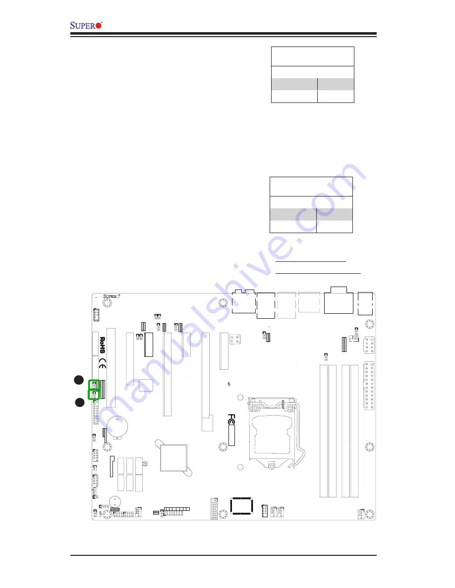
A. ME Recovery Mode
B. ME Manufacturing Mode

ME Manufacturing Mode (JPME2)

Close pins 2-3 of JPME2 to enable ME Manu

-

facturing  Mode.  See  the  table  on  the  right 
for  jumper  settings.    Note:  ME  Manufactur

-

ing Mode may be enabled without changing 
this  jumper  through  the  BIOS  setup.    See 
PCH-FW Configuration -> Firmware Update 
Configuration  in  the  BIOS  Setup.    The  /ME 
parameter must be specified when updating 
with the DOS utility.

ME Recovery Mode (JPME1)

Close pins 2-3 of JPME1 to enable ME Re

-

covery Mode. See the table on the right for 
jumper settings.

JPME2

Jumper Settings

Both Jumpers     Definition     

Pins 1-2

Disabled

Pins 2-3

Enabled

JPME1

Jumper Settings

Both Jumpers     Definition     

Pins 1-2

Disabled

Pins 2-3

Enabled

Summary of Contents for Supero X9SAE

Page 1: ...X9SAE X9SAE V USER S MANUAL Revision 1 0...

Page 2: ...ING OR RECOVERING SUCH HARDWARE SOFTWARE OR DATA Any disputes arising between manufacturer and customer shall be governed by the laws of Santa Clara County in the State of California USA The State of...

Page 3: ...ucts for processor and memory support updates This product is intended to be installed and serviced by professional technicians Manual Organization Chapter 1 describes the features specifications and...

Page 4: ...rictly followed to prevent catastrophic system failure or to avoid bodily injury Warning Critical information to prevent damage to the components or data loss Important Important information given to...

Page 5: ...s Super Micro Computer B V Het Sterrenbeeld 28 5215 ML s Hertogenbosch The Netherlands Tel 31 0 73 6400390 Fax 31 0 73 6416525 Email sales supermicro nl General Information support supermicro nl Techn...

Page 6: ...ith Firmware Control 1 11 Environmental Temperature Control 1 11 System Resource Alert 1 12 1 5 ACPI Features 1 12 Slow Blinking LED for Suspend State Indicator 1 12 1 6 Power Supply 1 12 1 7 Super I...

Page 7: ...OM1 2 18 Front Control Panel 2 19 Front Control Panel Pin Definitions 2 20 Power LED 2 20 HDD LED 2 20 NIC1 NIC2 LAN1 LAN2 2 21 Overheat OH Fan Fail 2 21 Reset Button 2 22 Power Button 2 22 2 6 Connec...

Page 8: ...ures 3 1 Before Power On 3 1 No Power 3 1 No Video 3 2 Memory Errors 3 2 Losing the System s Setup Configuration 3 2 3 2 Technical Support Procedures 3 3 3 3 Frequently Asked Questions 3 4 3 4 Battery...

Page 9: ...r Button Function 4 5 Restore on AC Power Loss 4 5 Deep Sx Power Policies 4 5 Processor Clock Options 4 5 Clock Spread Spectrum 4 5 Hardware Prefetcher 4 6 Adjacent Cache Line Prefetch 4 6 Intel Virtu...

Page 10: ...ons 4 10 Legacy USB Support 4 10 Port 60 64 Emulation 4 10 BIOS EHCI Hand Off 4 10 XHCI Hand off 4 10 Azalia HD Audio 4 11 Frontside Audio Mode 4 11 IDE SATA Configuration 4 11 SATA Mode 4 11 PCIe PCI...

Page 11: ...T Support 4 17 PCH FW Configuration 4 17 Firmware Update Configuration 4 17 AMT Configuration 4 17 Intel AMT 4 17 BIOS Hotkey Pressed 4 17 MEBx Selection Screen 4 17 Hide Un configure ME Confirmation...

Page 12: ...es and Exit 4 23 Save Changes and Reset 4 23 Discard Changes 4 23 Restore Defaults 4 23 Save As User Defaults 4 23 Restore User Defaults 4 24 Boot Override 4 24 Appendix A BIOS Error Beep Codes A 1 BI...

Page 13: ...etail to provide you with the highest standards in quality and performance Please check that the following items have all been included with your motherboard If anything listed here is damaged or miss...

Page 14: ...therboard Image Note All graphics shown in this manual were based upon the latest PCB Revision available at the time of publishing of the manual The motherboard you ve received may or may not look exa...

Page 15: ...AC CODE BAR CODE MH3 MH4 MH9 MH5 MH1 MH2 MH6 MH7 MH8 1 2 RST 2 3 NMI JWD1 JPL1 2 3 DISABLE 1 2 ENABLE 2 3 ME MANUFACTURING MODE 1 2 NORMAL JPME1 2 3 ME RECOVERY JPME2 1 2 NORMAL JPW3 JPL2 1 2 Enable 2...

Page 16: ...S CLEAR SPEAKER 1 4 JD1 BUZZER 3 4 JL1 CHASSIS INTRUSION PWR RST JF1 ON LED X OH FF NIC2 NIC1 HDD PWR LED LED BUZZER POWER LED JLED FAN3 FAN2 FAN1 CPU FAN ALWAYS POPULATE BLUE SOCKET FIRST AUDIO FP JP...

Page 17: ...Headers Pins 1 2 Enabled JWD1 Watch Dog Timer Reset Pins 1 2 Reset X9SAE Motherboard Series LED Indicators LED Description Color State Status LED1 Onboard Standby PWR LED Green Solid on Power On Back...

Page 18: ...t RJ45 Ports LAN1 2 S PDIF IN S PDIF OUT SPDIF Sony Philips Digital Interface In Out Headers JSD1 SATA DOM Device_On_Module Power Connector SLOT1 PCI 33MHz Slot SLOT2 PCI E 2 0 x4 in x8 Slot SLOT3 SLO...

Page 19: ...V only One 1 PCI 33 MHz slots 5 Volts Network Connections Two 2 Gigabit Ethernet Controllers LAN1 Intel 82579LM LAN2 Intel 82574L Two 2 RJ 45 Rear I O Panel Connectors with Link and Activity LEDs I O...

Page 20: ...r recovery PC Health Monitoring CPU Monitoring Onboard voltage monitors for 1 8V 3 3V 5V 12V 3 3V Stdby 5V Stdby VBAT HT Memory Chipset CPU 4 2 phase switching voltage regulator CPU System overheat LE...

Page 21: ...SLOT 7 33MHz 5V PCI PCI SLOT 1 4 SATA II PORTS SATA II 300MB s 8 USB2 0 PORTS USB2 0 480Mbps 2 SATA III PORTS SATA III 600MB s GLAN2 82574L PCIe2 0_x1 2 5GT s RJ45 RJ45 PCIe2 0_x1 2 5GT s GLAN1 82579L...

Page 22: ...y level price points Enhanced performance and energy efficiency Support for ECC Memory Better data integrity and system reliability through automatic data correction Intel Rapid Storage Technology Int...

Page 23: ...or an error message is sent to the screen The user can adjust the voltage thresholds to define the sensitivity of the voltage monitor Fan Status Monitor with Firmware Control PC health monitoring in...

Page 24: ...y and an operating system independent interface for configuration control ACPI leverages the Plug and Play BIOS data structures while providing a processor architecture independent implementation that...

Page 25: ...oose to install a line filter to shield the computer from noise It is recommended that you also install a power surge protector to help avoid problems caused by power surges 1 7 Super I O The Super I...

Page 26: ...1 14 X9SAE Motherboard Series User s Manual Notes...

Page 27: ...edges only do not touch its components peripheral chips memory modules or gold contacts When handling chips or modules avoid touching their pins Put the motherboard and peripherals back into their ant...

Page 28: ...If you buy a CPU separately make sure that you use an Intel certified multi directional heatsink only Make sure to install the system board into the chassis before you install the CPU heatsink When r...

Page 29: ...hold the CPU at the North center edge and the South center edge of the CPU 4 Align the CPU key that is the semi circle cutouts against the socket keys Once it is aligned carefully lower the CPU strai...

Page 30: ...may damage your CPU Instead open the load plate again and double check that the CPU is aligned properly CPU properly installed Load lever locked into place 5 Do not rub the CPU against the surface or...

Page 31: ...th other compo nents 3 Inspect the CPU Fan wires to make sure that the wires are routed through the bottom of the heatsink 4 Remove the thin layer of the protec tive film from the heatsink Caution CPU...

Page 32: ...ing holes until you hear a click Also make sure to orient each fastener so that the narrow end of the groove is pointing outward 8 Repeat Step 7 to insert all four heatsink fasteners into the mounting...

Page 33: ...U or other components Active Heatsink Removal 1 Unplug the power cord from the power supply 2 Disconnect the heatsink fan wires from the CPU fan header 3 Use your finger tips to gently press on the fa...

Page 34: ...1 1 2 19 20 JPCIE7 DIMM1 DIMM4 DIMM3 DIMM2 102 JPCI1 A1 B1 B2 JPCIE9 JUSBLAN2 JAUDIO1 J32 J15 2 1 7 J13 10 2 1 7 JD1 4 1 4 1 SP1 JWD1 JPL1 1 3 JPME2 1 3 JPME1 1 3 JPUSB1 1 3 JPUSB2 1 3 1 3 JCPUVRD_SMB...

Page 35: ...2GB 4GB 2GB 2GB 2GB 2GB 8GB 4GB 4GB 8GB 4GB 4GB 4GB 4GB 16GB 8GB 8GB 16GB 8GB 8GB 8GB 8GB 32GB Note Due to memory allocation to system devices the amount of memory that remains available for operation...

Page 36: ...rea Reserved for the chipset 2 MB 3 99 I O APIC 4 Kbytes 4 KB 3 99 PCI Enumeration Area 1 256 MB 3 76 PCI Express 256 MB 256 MB 3 51 PCI Enumeration Area 2 if needed Aligned on 256 MB boundary 512 MB...

Page 37: ...B1 WAKE UP 2 3 Disable 1 2 Enable JPUSB2 USB2 WAKE UP 2 3 Disable JPAC1 PCH SLOT2 PCI E 2 0 X4 INX8 CPU1 SLOT7 PCI E 2 0 X4 FANA USB2 3 CMOS CLEAR SPEAKER 1 4 JD1 BUZZER 3 4 JL1 CHASSIS INTRUSION PWR...

Page 38: ...standoffs in the chassis as needed 5 Install the motherboard into the chassis carefully to avoid damaging other motherboard components 6 Using the Philips screwdriver insert a Philips head 6 screw in...

Page 39: ...AKER 1 4 JD1 BUZZER 3 4 JL1 CHASSIS INTRUSION PWR RST JF1 ON LED X OH FF NIC2 NIC1 HDD PWR LED LED BUZZER POWER LED JLED FAN3 FAN2 FAN1 CPU FAN ALWAYS POPULATE BLUE SOCKET FIRST AUDIO FP JPAC1 AUDIO 1...

Page 40: ...VCC 5V 5 KB Clock 5 Mouse Clock 6 No Connection 6 No Connection VCC with 1 5A PTC current limit Keyboard Mouse For a PS 2 keyboard cable a PS 2 Mouse cable or a PS 2 Y cable optional For a USB keyboar...

Page 41: ...F Disable ON Enable KB MOUSE USB8 9 CPU DIMMA1 DIMMB2 DIMMA2 DIMMB1 X9SAE REV 1 01 DESIGNED IN USA A Backpanel USB 2 0 9 B Backpanel USB 2 0 8 C Backpanel USB 2 0 13 D Backpanel USB 2 0 10 E Backpanel...

Page 42: ...7 Ground 9 TD3 88 Ground NC No Connection A LAN1 B LAN2 A SPDIF_Out B Surround_Out C CEN LFE_Out D Mic_In E Line Out F Line_In A B E A B C F D Back Panel High Definition Audio HD Audio This motherboar...

Page 43: ...1 JI2C2 1 JI2C1 JUSB4 11 10 19 1 B49 B48 A49 A48 Tested to Comply With FCC Standards FOR HOME OR OFFICE USE MAC CODE BAR CODE MH3 MH4 MH9 MH5 MH1 MH2 MH6 MH7 MH8 1 2 RST 2 3 NMI JWD1 JPL1 2 3 DISABLE...

Page 44: ...le not included VGA Port A VGA port is located next to the USB ports on the I O backpanel Use this port to con nect to a compatible VGA display A B A HDMI Ports B VGA Port C COM1 Port Serial Port COM1...

Page 45: ...ZZER 3 4 JL1 CHASSIS INTRUSION PWR RST JF1 ON LED X OH FF NIC2 NIC1 HDD PWR LED LED BUZZER POWER LED JLED FAN3 FAN2 FAN1 CPU FAN ALWAYS POPULATE BLUE SOCKET FIRST AUDIO FP JPAC1 AUDIO 1 2 ENABLE 2 3 D...

Page 46: ...ED connection is located on pins 15 and 16 of JF1 Refer to the table on the right for pin definitions Power LED Pin Definitions JF1 Pin Definition 15 5V 16 Ground A PWR LED B HDD LED A B HDD LED The H...

Page 47: ...ons JF1 Pin Definition 9 11 Vcc 10 12 Ground C A NIC1 LED B NIC2 LED C OH Fan Fail Overheat OH Fan Fail Connect an LED cable to OH Fan Fail connections on pins 7 and 8 of JF1 to provide warnings for c...

Page 48: ...to the table on the right for pin definitions Power Button Pin Definitions JF1 Pin Definition 1 Signal 2 3V Standby Reset Button The Reset Button connection is located on pins 3 and 4 of JF1 Attach it...

Page 49: ...B0 1 USB4 5 USB10 13 USB3 0 3 4 COM1 VGA HDMI1 2 LAN2 LAN1 I SATA0 I SATA1 I SATA2 I SATA3 I SATA4 I SATA5 PCH SLOT3 PCI E 2 0 X1 CPU1 SLOT4 PCI E 3 0 X8 INX16 CPU1 SLOT6 PCI E 3 0 X16 PCH SLOT5 PCI E...

Page 50: ...AUDIO 1 2 ENABLE 2 3 DISABLE JPW2 JPW1 COM2 SLOT1 PCI 33MHZ USB11 12 USB0 1 USB4 5 USB10 13 USB3 0 3 4 COM1 VGA HDMI1 2 LAN2 LAN1 I SATA0 I SATA1 I SATA2 I SATA3 I SATA4 I SATA5 PCH SLOT3 PCI E 2 0 X1...

Page 51: ...ON PWR RST JF1 ON LED X OH FF NIC2 NIC1 HDD PWR LED LED BUZZER POWER LED JLED FAN3 FAN2 FAN1 CPU FAN ALWAYS POPULATE BLUE SOCKET FIRST AUDIO FP JPAC1 AUDIO 1 2 ENABLE 2 3 DISABLE JPW2 JPW1 COM2 SLOT1...

Page 52: ...RST JF1 ON LED X OH FF NIC2 NIC1 HDD PWR LED LED BUZZER POWER LED JLED FAN3 FAN2 FAN1 CPU FAN ALWAYS POPULATE BLUE SOCKET FIRST AUDIO FP JPAC1 AUDIO 1 2 ENABLE 2 3 DISABLE JPW2 JPW1 COM2 SLOT1 PCI 33...

Page 53: ...JD1 BUZZER 3 4 JL1 CHASSIS INTRUSION PWR RST JF1 ON LED X OH FF NIC2 NIC1 HDD PWR LED LED BUZZER POWER LED JLED FAN3 FAN2 FAN1 CPU FAN ALWAYS POPULATE BLUE SOCKET FIRST AUDIO FP JPAC1 AUDIO 1 2 ENABLE...

Page 54: ...FAN3 FAN2 FAN1 CPU FAN ALWAYS POPULATE BLUE SOCKET FIRST AUDIO FP JPAC1 AUDIO 1 2 ENABLE 2 3 DISABLE JPW2 JPW1 COM2 SLOT1 PCI 33MHZ USB11 12 USB0 1 USB4 5 USB10 13 USB3 0 3 4 COM1 VGA HDMI1 2 LAN2 LA...

Page 55: ...UT 1 JL1 1 JI2C2 1 JI2C1 JUSB4 11 10 19 1 B49 B48 A49 A48 Tested to Comply With FCC Standards FOR HOME OR OFFICE USE MAC CODE BAR CODE MH3 MH4 MH9 MH5 MH1 MH2 MH6 MH7 MH8 1 2 RST 2 3 NMI JWD1 JPL1 2 3...

Page 56: ...1 ON LED X OH FF NIC2 NIC1 HDD PWR LED LED BUZZER POWER LED JLED FAN3 FAN2 FAN1 CPU FAN ALWAYS POPULATE BLUE SOCKET FIRST AUDIO FP JPAC1 AUDIO 1 2 ENABLE 2 3 DISABLE JPW2 JPW1 COM2 SLOT1 PCI 33MHZ USB...

Page 57: ...N LED X OH FF NIC2 NIC1 HDD PWR LED LED BUZZER POWER LED JLED FAN3 FAN2 FAN1 CPU FAN ALWAYS POPULATE BLUE SOCKET FIRST AUDIO FP JPAC1 AUDIO 1 2 ENABLE 2 3 DISABLE JPW2 JPW1 COM2 SLOT1 PCI 33MHZ USB11...

Page 58: ...LED X OH FF NIC2 NIC1 HDD PWR LED LED BUZZER POWER LED JLED FAN3 FAN2 FAN1 CPU FAN ALWAYS POPULATE BLUE SOCKET FIRST AUDIO FP JPAC1 AUDIO 1 2 ENABLE 2 3 DISABLE JPW2 JPW1 COM2 SLOT1 PCI 33MHZ USB11 1...

Page 59: ...CPU FAN ALWAYS POPULATE BLUE SOCKET FIRST AUDIO FP JPAC1 AUDIO 1 2 ENABLE 2 3 DISABLE JPW2 JPW1 COM2 SLOT1 PCI 33MHZ USB11 12 USB0 1 USB4 5 USB10 13 USB3 0 3 4 COM1 VGA HDMI1 2 LAN2 LAN1 I SATA0 I SAT...

Page 60: ...CIE5 J30 5 1 HDMI_ B1 C3102 JSPDIF_IN JSPDIF_OUT 1 JL1 1 JI2C2 1 JI2C1 JUSB4 11 10 19 1 B49 B48 A49 A48 Tested to Comply With FCC Standards FOR HOME OR OFFICE USE MAC CODE BAR CODE MH3 MH4 MH9 MH5 MH1...

Page 61: ...LUE SOCKET FIRST AUDIO FP JPAC1 AUDIO 1 2 ENABLE 2 3 DISABLE JPW2 JPW1 COM2 SLOT1 PCI 33MHZ USB11 12 USB0 1 USB4 5 USB10 13 USB3 0 3 4 COM1 VGA HDMI1 2 LAN2 LAN1 I SATA0 I SATA1 I SATA2 I SATA3 I SATA...

Page 62: ...PWR RST JF1 ON LED X OH FF NIC2 NIC1 HDD PWR LED LED BUZZER POWER LED JLED FAN3 FAN2 FAN1 CPU FAN ALWAYS POPULATE BLUE SOCKET FIRST AUDIO FP JPAC1 AUDIO 1 2 ENABLE 2 3 DISABLE JPW2 JPW1 COM2 SLOT1 PCI...

Page 63: ...ents 2 Make sure that there are no short circuits between the motherboard and chassis 3 Disconnect all ribbon wire cables from the motherboard including those for the keyboard and mouse Also be sure t...

Page 64: ...o it is recommended that you use the memory modules of the same type and speed for all DIMMs in the system Do not use memory modules of different sizes different speeds and different types on the same...

Page 65: ...be downloaded from our website at http www supermi cro com support bios Note Not all BIOS can be flashed Some cannot be flashed it depends on the boot block code of the BIOS 3 If you ve followed the i...

Page 66: ...from your bootable device or USB pen thumb drive Use the following format F ami bat BIOS ROM filename xxx Enter Note Always use the file named ami bat to update the BIOS and insert a space between am...

Page 67: ...et drivers for Windows security programs and audio drivers Question Why do I get an error message IASTOR SYS read error and press F6 to install Intel RAID driver when installing Windows on my motherbo...

Page 68: ...tery in any way a damaged battery may release hazardous materials into the environment Do not discard a used battery in the garbage or a public landfill Please comply with the regulations set up by y...

Page 69: ...ton and mailed prepaid or hand carried Shipping and handling charges will be applied for all orders that must be mailed when service is complete This warranty only covers normal consumer use and does...

Page 70: ...3 8 X9SAE Motherboard Series User s Manual Notes...

Page 71: ...options that can be configured Grayed out options cannot be configured Options in blue can be configured by the user The right frame displays the key legend Above the key legend is an area reserved fo...

Page 72: ...S update If you have to update the BIOS do not shut down or reset the system while the BIOS is updating This is to avoid possible boot failure 4 2 Main Setup When you first enter the AMI BIOS Setup Ut...

Page 73: ...move between fields The date must be entered in Day MM DD YY format The time is entered in HH MM SS format Note The time is in the 24 hour format For example 5 30 P M appears as 17 30 00 The following...

Page 74: ...F1 key is pressed if an error occurs The options are Disabled and Enabled Interrupt 19 Capture Interrupt 19 is the software interrupt that handles the boot disk function When this item is set to Enab...

Page 75: ...verride and Instant Off Restore on AC Power Loss Use this feature to set the power state after a power outage Select Power Off for the system power to remain off after a power loss Select Power On for...

Page 76: ...u will need to power off and restart the system for the change to take effect Please refer to Intel s web site for detailed information Execute Disable Bit Capability Available when supported by the O...

Page 77: ...Long Duration Power Limit is maintained Long Duration Maintained Use this feature to set the time value when the Long Duration Power Limit is maintained Recommended Short Duration Power Limit The syst...

Page 78: ...by reporting the I O device assignments to VMM through the DMAR ACPI Tables This feature offers fully protected I O resource sharing across the Intel platforms providing the user with greater reliabi...

Page 79: ...phics Device IGD The options are Disabled 32M 64M 96M 128M 160M 192M 224M 256M 288M 320M 352M 384M 416M 448M 480M 512M and 1024M DVMT Total Gfx Mem This feature selects the total memory size for the I...

Page 80: ...feature enables support for legacy USB devices Select Auto to dis able legacy support if USB devices are not present Select Disable to have USB devices available only for EFI applications The options...

Page 81: ...Mode AHCI Mode and RAID Mode AHCI Mode The following items are displayed when AHCI Mode is selected Aggressive LPM Support This feature Enables or Disables Agressive Link Power Management sup port fo...

Page 82: ...ect 64 to set the PCI latency to 64 PCI bus clock cycles The options are 32 PCI Bus Clocks 64 PCI Bus Clocks 96 PCI Bus Clocks 128 PCI Bus Clocks 160 PCI Bus Clocks 192 PCI Bus Clocks 224 PCI Bus Cloc...

Page 83: ...Serial Port 1 Serial Port 2 Select Enabled to enable the onboard serial port The options are Enabled and Disabled Serial Port 1 Serial Port 2 Settings This option specifies the base I O port address...

Page 84: ...or Disabled Recorder Mode Disabled or Enabled Resolution 100x31 Enabled or Disabled Legacy OS Redirection Resolution 80x25 or 80x24 puTTY Keypad VT100 LINUX XTERM6 SCO ESCN VT400 Serial Port for Out...

Page 85: ...ture is well below the CPU Temperature Tolerance The mother board fans and CPU will run normally as configured in the BIOS Fan Speed Control User intervention No action required Medium The processor i...

Page 86: ...ded in the CPU The High Performance Event Timer is used to replace the 8254 Programmable Interval Timer The options are Enabled and Disabled Suspend Mode This setting allows you to configure the ACPI...

Page 87: ...and Disabled BIOS Hotkey Pressed This option enables or disables the BIOS Hotkey The options are Enabled and Disabled MEBx Selection Screen This option enables or disables the MEBx selection screen Th...

Page 88: ...Timer Allows AMT to reset or power down the system if the operating system or BIOS hangs or crashes The options are Disabled and Enabled OS WatchDog Timer BIOS WatchDog Timer These options appear if...

Page 89: ...Event Logging during boot The options are Enabled and Disabled Erase Settings Erase Event Log This option erases all logged events The options are No Yes Next reset and Yes Every reset When Log is Fu...

Page 90: ...iple Event Time Window METW defines number of minutes must pass between duplicate log events before MECI is incremented This is in minutes from 0 to 99 The default value is 60 View SmBIOS Event Log Th...

Page 91: ...D ROM Drive BBS Priorities Hard Drive BBS Priorities These options appear only if any of the devices are installed and detected by the BIOS This feature sets the order of legacy devices in their parti...

Page 92: ...word Select Screen Select Item Enter Select Change Opt F1 General Help F2 Previous Values F3 Optimized Defaults F4 Save Exit ESC Exit Version x xx xxxx Copyright C 2011 American Megatrends Inc Set Adm...

Page 93: ...ram Restore Defaults To set this feature select Restore Defaults from the Exit menu and press Enter These are factory settings designed for maximum system stability but not for maximum performance Sav...

Page 94: ...his feature select Restore User Defaults from the Exit menu and press En ter Use this feature to retrieve user defined settings that were saved previously Boot Override Set this feature to override a...

Page 95: ...rror oc curs you should consult with your system manufacturer for possible repairs These fatal errors are usually communicated through a series of audible beeps The numbers on the fatal error list cor...

Page 96: ...A 2 X9SAE Motherboard Series User s Manual Notes...

Page 97: ...th a CD on it allows you to view the entire contents of the CD Note 2 When making a storage driver diskette by booting into a Driver CD please set the SATA Configuration to Compatible Mode and configu...

Page 98: ...octor III displays crucial system information such as CPU temperature system voltages and fan status See the Figure below for a display of the SuperDoctor III interface Note 1 The default user name an...

Page 99: ...I Remote Control Note The SuperDoctor III software and manual may be downloaded from our Website at http www supermicro com products accessories software SuperDoctorIII cfm For Linux we still recommen...

Page 100: ...B 4 X9SAE Motherboard Series User s Manual Notes...

Page 101: ...n the add on card to boot up the system UEFI offers a clean hand off control to a computer system at bootup C 2 How to Recover the UEFI BIOS Image the Main BIOS Block An AMIBIOS flash chip consists of...

Page 102: ...ge file into the disc Root Directory of a USB device or a writeable CD DVD Note If you cannot locate the Super ROM file in your driver disk visit our website at www supermicro com to download the BIOS...

Page 103: ...and press the Enter key You will see the progress of BIOS Recovery as shown in the screen below Note Do not interrupt the process of BIOS flashing until it is com pleted 6 After the process of BIOS Re...

Page 104: ...seeing the message that BIOS update is completed unplug the AC pow er cable from the power supply to clear CMOS and then plug the AC power cable in the power supply again to power on the system 10 Pre...

Page 105: ...expected to result in significant injury or loss of life or catastrophic property damage Accordingly Supermicro disclaims any and all liability and should buyer use or sell such products for use in su...

Reviews: