background image

C-4

              X7QC3/X7QCE User's Manual

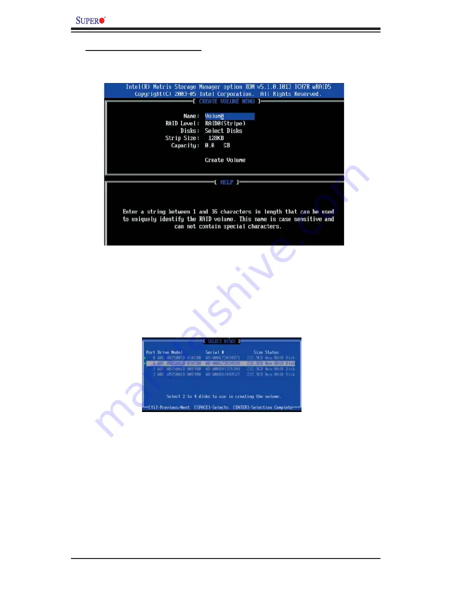
b. Specify a name for the RAID 0 set and press the <Tab> key or the <Enter> key 

to go to the next fi eld. (You can use the <Esc> key to select the previous menu.)

c. When RAID Level item is highlighted, press the <Up Arrow>, <Down Arrow> keys 

to select RAID 0 (Stripe) and hit <Enter>. 

d. When the Disks item is highlighted, press <Enter> to select the HDD to confi gure 

as RAID.  The following pop-up screen (*See the note on Page C-3) displays:

e. Use  the <Up Arrow>, <Down Arrow> keys to highlight a drive and press <Space> 

to select it. A triangle appears to confi rm the selection of the drive.

f. Use  the <Up Arrow>, <Down Arrow> keys to select the stripe size, ranging from 

4 KB to 128 KB for the RAID 0 array, and hit <Enter>. (N

ote

: For a server, please 

use a lower stripe size, and for a multimedia system, use a higher stripe size. The 

default stripe size is 128 KB.)

g. Press <Enter> when the Create Volume item is highlighted. A warning message 

displays.

h. When asked "Are you sure you want to create this volume (Y/N), press "Y" to 

create the RAID volume, or type "N" to go back to the Create Volume menu.

Creating a RAID 0 Volume:

a. Select "Create RAID Volume" from the main menu and press the <Enter> key. 

The following screen will appear:

Summary of Contents for Supero X7QC3

Page 1: ...X7QC3 USER S MANUAL Revision 1 0 SUPER X7QCE...

Page 2: ...CRO COMPUTER INC SHALL NOT HAVE LIABILITY FOR ANY HARDWARE SOFTWARE OR DATA STORED OR USED WITH THE PRODUCT INCLUDING THE COSTS OF REPAIRING REPLACING INTEGRATING INSTALLING OR RECOVERING SUCH HARDWAR...

Page 3: ...This product is intended to be professionally installed Manual Organization Chapter 1 describes the features speci cations and performance of the mainboard and provides detailed information about the...

Page 4: ...th Monitoring 1 10 1 5 ACPI Features 1 11 1 6 Power Supply 1 12 1 7 Super I O 1 12 Chapter 2 Installation 2 1 Static Sensitive Devices 2 1 Precautions 2 1 Unpacking 2 1 2 2 Processor and Heatsink Inst...

Page 5: ...Alarm Reset 2 20 Power SMB Connector 2 20 Overheat Fan Fail LED 2 21 Compact Flash Power Connector 2 21 Keylock 2 22 IPMB Header 2 22 2 6 Jumper Settings 2 23 Explanation of Jumpers 2 23 GLAN Enable D...

Page 6: ...t Procedures 3 2 3 3 Frequently Asked Questions 3 3 3 4 Returning Merchandise for Service 3 3 Chapter 4 BIOS 4 1 Introduction 4 1 4 2 Main Setup 4 2 4 3 Advanced Setup 4 3 4 4 Boot Setup 4 20 4 5 Secu...

Page 7: ...ity and performance Check that the following items have all been included with your motherboard If anything listed here is damaged or missing contact your retailer All are included in the Retail Box O...

Page 8: ...r Micro Computer B V Het Sterrenbeeld 28 5215 ML s Hertogenbosch The Netherlands Tel 31 0 73 6400390 Fax 31 0 73 6416525 Email sales supermicro nl General Information support supermicro nl Technical S...

Page 9: ...Image Note The drawings and graphics shown in this manual were based on the latest PCB Revision available at the time of publishing of the manual The motherboard you ve received may or may not look ex...

Page 10: ...M A1 Branch 0 Channel 0 DIMM A2 Branch 0 Channel 0 DIMM A3 Branch 0 Channel 0 DIMM A4 Branch 0 Channel 0 DIMM A5 Branch 0 Channel 0 DIMM A6 Branch 0 Channel 0 DIMM B1 Branch 0 Channel 1 DIMM B2 Branch...

Page 11: ...Connector J15 J16 Serial General Purpose Input Output Headers 1 2 J17 Floppy Disk Drive Connector J19 SIMSO Slot J3P1 PWR Supply Module Failure JAR Alarm Reset JCOM1 JCOM2 COM1 COM2 Serial Port and S...

Page 12: ...IOS 8 Mb AMI Flash ROM APM 1 2 DMI 2 3 PCI 2 2 ACPI 1 0 Plug and Play PnP USB Keyboard support Hardware BIOS Virus Protection and SMBIOS 2 3 PC Health Monitoring Onboard voltage monitors for CPU cores...

Page 13: ...Giga bit LAN ports w IOAT supported One EIDE Ultra DMA 100 bus master interface One oppy port interface Two COM ports 1 header 1 port Up to four USB 2 0 Universal Serial Bus 2 ports 1 Header ATI ES10...

Page 14: ...PORT 0 HCK PORT 1 PEXH PCI X 133 PCI 32 33 USB LSI 1068E ATI ES1000 32MB DDR2 SDRAM DB15VGA Port 480Mb S 480Mb S 480Mb S 480Mb S 480Mb S 480Mb S IDE S IDE M 17 GB s for 533MHz 21 GB s for 667MHz North...

Page 15: ...ss and one x4 ESI interface ESI to the ESB2 In addition the 7300 chipset offers a wide range of Reliability Availability Serviceability RAS features including memory interface ECC x4 x8 Single Device...

Page 16: ...screen The user can adjust the voltage thresholds to de ne the sensitivity of the voltage monitor Fan Status Monitor with Firmware Control The PC health monitor can check the RPM status of the cooling...

Page 17: ...e for con guration control ACPI leverages the Plug and Play BIOS data structures while providing a processor architecture indepen dent implementation that is compatible with Windows 2000 Windows XP an...

Page 18: ...er supply to the CPU Also your power supply must supply 1 5A for the Ethernet ports It is strongly recommended that you use a high quality power supply that meets ATX power supply Speci cation 2 02 or...

Page 19: ...ed speed with baud rates of 250 Kbps 500 Kbps or 1 Mbps which support higher speed modems The Super I O provides functions that comply with ACPI Advanced Con guration and Power Interface which include...

Page 20: ...1 14 X7QC3 X7QCE User s Manual Notes...

Page 21: ...not touch its components peripheral chips memory modules or gold contacts When handling chips or modules avoid touching their pins Put the motherboard and peripherals back into their antistatic bags...

Page 22: ...ink and fan See below 4 When purchasing a motherboard with an Xeon 7300 7200 Quad Core Dual Core INT mPGA CPU Socket make sure that the CPU plastic cap is in place and none of the CPU Socket pins are...

Page 23: ...marked with a triangle Note When using only one CPU install it into CPU socket 1 Please note that sockets 2 3 and 4 will be automatically disabled if only one CPU is used 3 Press the lever down until...

Page 24: ...e follow the instructions on the next page to uninstall the heatsink to avoid damaging the CPU or the CPU socket Installation and Removal of the Heatsink CEK Passive Heatsink Screw 1 Screw 2 To Uninst...

Page 25: ...down on the DIMM module until it snaps into place in the slot Repeat for all modules see step 1 above X7QC3 To Install Insert module vertically and press down until it snaps into place Pay attention t...

Page 26: ...uired in mirrored mode on both branches Memory Configuration Table Branch 0 Branch 1 Channel 0 Bank 0 Channel 1 Bank 1 Channel 2 Bank 2 Channel 3 Bank 3 2 DIMMs A1 B1 4 DIMMs A1 B1 C1 D1 8 DIMMs A1 A2...

Page 27: ...for the colors and locations of the various I O ports A Back Panel Connectors IO Ports Figure 2 3 Back Panel I O Port Locations and De nitions Back Panel Connectors 1 Keyboard Purple 2 PS 2 Mouse Gree...

Page 28: ...de signed speci cally for use with Supermicro server chassis See Figure 2 4 for the descriptions of the various control panel buttons and LED indicators Refer to the following section for description...

Page 29: ...19 and 20 of JF1 Refer to the table on the right for pin de nitions Power Button OH Fan Fail LED 1 NIC1 LED Reset Button 2 HDD LED Power LED Reset PWR Vcc Vcc Vcc Vcc Ground Ground 19 20 Vcc X Ground...

Page 30: ...GLAN Port2 is on Pins 9 and 10 Attach the NIC LED cables to display network activity status Refer to the table on the right for pin de nitions HDD LED The HDD LED connection is located on pins 13 and...

Page 31: ...de advanced warnings of chassis overheating or fan failure Refer to the table on the right for pin de nitions Power Fail LED The Power Fail LED connection is located on pins 5 and 6 of JF1 Re fer to t...

Page 32: ...to function as a suspend button with a setting in the BIOS see Chapter 4 To turn off the power when set to suspend mode press the button for at least 4 seconds Refer to the table on the right for pin...

Page 33: ...nel 2 DIMM C4 Branch 1 Channel 2 DIMM C5 Branch 1 Channel 2 DIMM C6 Branch 1 Channel 2 JUSB3 I Button Battery SAS 4i 4 7 SAS 4i 0 3 PCI Slot3 PCI E X8 in X8 slot PCI Slot6 PCI E x8 in x16 slot GLAN2 G...

Page 34: ...ED2 CPLED1 BIOS SAS CTRL Intel ESB2 South Bridge JWD1 JOH1 DIMM C3 Branch 1 Channel 2 DIMM C4 Branch 1 Channel 2 DIMM C5 Branch 1 Channel 2 DIMM C6 Branch 1 Channel 2 JUSB3 I Button Battery SAS 4i 4 7...

Page 35: ...Battery SAS 4i 4 7 SAS 4i 0 3 PCI Slot3 PCI E X8 in X8 slot PCI Slot6 PCI E x8 in x16 slot GLAN2 GLAN1 CPU1 X7QC3 CPU0 CPU 3 CPU 2 Intel 7300 North Bridge Fan Headers The X7QC3 X7QCE has nine CPU cha...

Page 36: ...l 3 DIMM D5 Branch 1 Channel 3 DIMM D6 Branch 1 Channel 3 CPLED0 CPLED2 CPLED1 BIOS SAS CTRL Intel ESB2 South Bridge JWD1 JOH1 DIMM C3 Branch 1 Channel 2 DIMM C4 Branch 1 Channel 2 DIMM C5 Branch 1 Ch...

Page 37: ...nch 1 Channel 3 DIMM D5 Branch 1 Channel 3 DIMM D6 Branch 1 Channel 3 CPLED0 CPLED2 CPLED1 BIOS SAS CTRL Intel ESB2 South Bridge JWD1 JOH1 DIMM C3 Branch 1 Channel 2 DIMM C4 Branch 1 Channel 2 DIMM C5...

Page 38: ...hannel 3 DIMM D3 Branch 1 Channel 3 DIMM D4 Branch 1 Channel 3 DIMM D5 Branch 1 Channel 3 DIMM D6 Branch 1 Channel 3 CPLED0 CPLED2 CPLED1 BIOS SAS CTRL Intel ESB2 South Bridge JWD1 JOH1 DIMM C3 Branch...

Page 39: ...1 Channel 3 DIMM D4 Branch 1 Channel 3 DIMM D5 Branch 1 Channel 3 DIMM D6 Branch 1 Channel 3 CPLED0 CPLED2 CPLED1 BIOS SAS CTRL Intel ESB2 South Bridge JWD1 JOH1 DIMM C3 Branch 1 Channel 2 DIMM C4 Br...

Page 40: ...IMM D4 Branch 1 Channel 3 DIMM D5 Branch 1 Channel 3 DIMM D6 Branch 1 Channel 3 CPLED0 CPLED2 CPLED1 BIOS SAS CTRL Intel ESB2 South Bridge JWD1 JOH1 DIMM C3 Branch 1 Channel 2 DIMM C4 Branch 1 Channel...

Page 41: ...J9 J8 J6 LES1 LES2 LE1 JD1 JIDE1 JIDE2 JKM1 JPW2 JPW3 JUSB1 JWF1 SP1 JBT1 JWOL1 J12 J3P1 JS6 JS5 JS4 JS3 JS2 JS1 PCI Slot5 PCI E x4 in x8 Slot J10 FAN3 VGA CTRL S I O JPW1 FAN1 JF1 LAN CTRL DIMM A1 B...

Page 42: ...hannel 0 DIMM A6 Branch 0 Channel 0 DIMM B1 Branch 0 Channel 1 DIMM B2 Branch 0 Channel 1 DIMM B3 Branch 0 Channel 1 DIMM B4 Branch 0 Channel 1 DIMM B5 Branch 0 Channel 1 DIMM B6 Branch 0 Channel 1 DI...

Page 43: ...DIMM D6 Branch 1 Channel 3 CPLED0 CPLED2 CPLED1 BIOS SAS CTRL Intel ESB2 South Bridge JWD1 JOH1 DIMM C3 Branch 1 Channel 2 DIMM C4 Branch 1 Channel 2 DIMM C5 Branch 1 Channel 2 DIMM C6 Branch 1 Channe...

Page 44: ...Branch 1 Channel 2 DIMM C4 Branch 1 Channel 2 DIMM C5 Branch 1 Channel 2 DIMM C6 Branch 1 Channel 2 JUSB3 I Button Battery SAS 4i 4 7 SAS 4i 0 3 PCI Slot3 PCI E X8 in X8 slot PCI Slot6 PCI E x8 in x1...

Page 45: ...M D6 Branch 1 Channel 3 CPLED0 CPLED2 CPLED1 BIOS SAS CTRL Intel ESB2 South Bridge JWD1 JOH1 DIMM C3 Branch 1 Channel 2 DIMM C4 Branch 1 Channel 2 DIMM C5 Branch 1 Channel 2 DIMM C6 Branch 1 Channel 2...

Page 46: ...OH1 DIMM C3 Branch 1 Channel 2 DIMM C4 Branch 1 Channel 2 DIMM C5 Branch 1 Channel 2 DIMM C6 Branch 1 Channel 2 JUSB3 I Button Battery SAS 4i 4 7 SAS 4i 0 3 PCI Slot3 PCI E X8 in X8 slot PCI Slot6 PCI...

Page 47: ...hannel 3 CPLED0 CPLED2 CPLED1 BIOS SAS CTRL Intel ESB2 South Bridge JWD1 JOH1 DIMM C3 Branch 1 Channel 2 DIMM C4 Branch 1 Channel 2 DIMM C5 Branch 1 Channel 2 DIMM C6 Branch 1 Channel 2 JUSB3 I Button...

Page 48: ...hannel 2 DIMM C5 Branch 1 Channel 2 DIMM C6 Branch 1 Channel 2 JUSB3 I Button Battery SAS 4i 4 7 SAS 4i 0 3 PCI Slot3 PCI E X8 in X8 slot PCI Slot6 PCI E x8 in x16 slot GLAN2 GLAN1 CPU1 X7QC3 CPU0 CPU...

Page 49: ...h 1 Channel 2 DIMM C2 Branch 1 Channel 2 DIMM D1 Branch 1 Channel 3 DIMM D2 Branch 1 Channel 3 DIMM D3 Branch 1 Channel 3 DIMM D4 Branch 1 Channel 3 DIMM D5 Branch 1 Channel 3 DIMM D6 Branch 1 Channel...

Page 50: ...ge JWD1 JOH1 DIMM C3 Branch 1 Channel 2 DIMM C4 Branch 1 Channel 2 DIMM C5 Branch 1 Channel 2 DIMM C6 Branch 1 Channel 2 JUSB3 I Button Battery SAS 4i 4 7 SAS 4i 0 3 PCI Slot3 PCI E X8 in X8 slot PCI...

Page 51: ...4 7 SAS 4i 0 3 PCI Slot3 PCI E X8 in X8 slot PCI Slot6 PCI E x8 in x16 slot GLAN2 GLAN1 CPU1 X7QC3 CPU0 CPU 3 CPU 2 Intel 7300 North Bridge IDE Drive Connectors Pin De nitions Pin De nition Pin De ni...

Page 52: ...2 32 X7QC3 X7QCE User s Manual Notes...

Page 53: ...rly seated Be sure to check all jumper settings as well No Power 1 Make sure that there are no short circuits between the motherboard and the chassis 2 Make sure that all jumpers are set to their defa...

Page 54: ...memory scheme is used you must install two modules at a time beginning with Bank 0 then Bank 1 and so on see Section 2 3 6 Check the position of the 115V 230V switch on the power supply 3 2 Technical...

Page 55: ...info on how to update your BIOS on our web site Also check the current BIOS revision and make sure it is newer than your BIOS before downloading Select your motherboard model and download the BIOS le...

Page 56: ...iled when service is complete This warranty only covers normal consumer use and does not cover damages in curred in shipping or from failure due to the alternation misuse abuse or improper maintenance...

Page 57: ...n white Often a text message will accompany it Note the AMIBIOS Setup Utility has default text messages built in Supermicro retains the option to include omit or change any of these text messages The...

Page 58: ...elect this option the AMIBIOS Setup Utility will automatically display the status of processors as shown below Type Speed Count System Memory This option allows the AMIBIOS Setup Utility to display th...

Page 59: ...bled This option allows the user to set the ratio between the CPU Core Clock and the FSB frequency The default setting is 6 Hardware Prefetcher Available when supported by the OS and the CPU If set to...

Page 60: ...o overwhelm the processor or damage the system during an attack Note For more information regarding hardware software support for this function please refer to Intel s and Microsoft s web sites Intel...

Page 61: ...512 bytes of data can be transferred per interrupt if the Block Mode is not used If the Block Mode is used data will be transferred of up to 64 KB per interrupt If set to Disabled data will be transfe...

Page 62: ...low the BIOS to use Ultra DMA mode 2 It has a data transfer rate of 33 3 MBs Select UDMA3 to allow the BIOS to use Ultra DMA mode 3 It has a data transfer rate of 66 6 MBs Select UDMA4 to allow the BI...

Page 63: ...n the system PCI Latency Timer This feature sets the latency Timer of each PCI device installed on a PCI bus Se lect 64 to set the PCI latency to 64 PCI clock cycles The default setting is 64 Allocate...

Page 64: ...are Enabled and Disabled Floppy Drive Swap Select Enabled to allow for oppy drive swap The default setting is Disabled Serial Port1 Address Serial Port2 Address This option speci es the base I O port...

Page 65: ...ve Branch Sequencing Branch Mirroring and Single Channel 0 Patrol Scrubbing Scrubbing is a process that allows the North Bridge to correct correctable memory errors found on FBD memory modules Select...

Page 66: ...nce caused by the components and will attempt to decrease the interference whenever needed The options are Enabled and Disabled Non Compliance Mode Select the Compliance Mode to enable the PCI Express...

Page 67: ...he device installed on the bus The options for Slot 1 are Auto 33 MHz PCI 66 MHz PCI 66 MHz PCI X 100 MHz PCI X and 133 MHz PCI X The options for Slot 2 are Auto 66 MHz PCI 100 MHz PCI X and 133 MHz P...

Page 68: ...Disable legacy support if there are no USB devices installed in the system The options are Disabled Enabled and Auto USB 2 0 Controller Mode This setting allows you to con gure the USB 2 0 Controller...

Page 69: ...ble the ACPI support for the operating system Advanced ACPI Con guration Use this feature to con gure advanced ACPI options Select Yes if the operating system supports ACPI Select No if the operating...

Page 70: ...ort speci ed by the user and automatically display the status of the IDE drive as detected by the BIOS APM Con guration This feature allows the user to con gure the Advanced Power Management set tings...

Page 71: ...off when the user presses the power button If set to the Suspend Mode the system will go into the Suspend mode when the user presses the power button The options are On Off and Suspend Advanced Resum...

Page 72: ...pin the fan speed will be controlled by Pulse Width Modulation PWM Select 3 pin if your chassis came with 3 pin fan headers Select 4 pin if your chassis came with 4 pin fan headers Select Workstation...

Page 73: ...llow the in structions given on the screen to select the MPS Revision Number The options are 1 1 and 1 4 PCI Express Con guration This section allows the user to con gure the PCI Express slots Active...

Page 74: ...tion The options are COM1 and COM2 Base Address IRQ This feature allows the user to set the Base Address and IRQ settings for COM1 or COM2 The default setting for COM1 is 3F8h 4 The default setting fo...

Page 75: ...Key Support This feature allows the user to select Enabled to enable the VT UTF8 Combination Key support for the ANSI VT100 Terminals The options are Enabled and Disabled Sredir Memory Display Delay T...

Page 76: ...e computer system to display the POST messages Select Enabled to allow the computer system to display the OEM logo AddOn ROM Display Mode This option allows the BIOS to display AddOn ROM read only mem...

Page 77: ...terrupt 19 The options are Enabled and Disabled Boots Graphic Adapter Priority This feature allows the user to select which graphics controller to be used as the primary boot device The options are Au...

Page 78: ...equence from available Remov able Drives 1st Drive 2nd Drive This option allow the user to specify the boot sequence for the rst Removable Drive and the second Removable Drive The options are 1st Flop...

Page 79: ...e Select No Access to prevent the user from entering the BIOS Setup Utility Select View Only to allow the user to enter the BIOS Setup Utility and view the settings The user is not allowed to make cha...

Page 80: ...n guration and reboot the computer Select Discard Changes and Exit from the Exit menu and press Enter Password Check Set to Setup to allow the system to perform a password check when the BIOS Setup is...

Page 81: ...Enter Then Select OK to allow the AMIBIOS Setup Utility to automatically load Optimal Defaults to the BIOS Settings The Optimal settings are designed for maximum system performance but may not work b...

Page 82: ...4 26 X7QC3 X7QCE User s Manual Notes...

Page 83: ...Keyboard controller failed test May require replacing keyboard controller Keyboard locked Unlock key switch Unlock the system to proceed Monitor type does not match CMOS Run SETUP Monitor type not co...

Page 84: ...Previous boot incomplete Default con guration used Previous POST did not complete successfully POST loads default values and offers to run Setup If the failure was caused by incorrect values and they...

Page 85: ...ServerBIOS2 test error Cannot generate software NMI Non Maskable Interrupt Fail Safe Timer NMI Failed ServerBIOS2 test error Fail Safe Timer takes too long Device Address Con ict Address con ict for...

Page 86: ...ested One or more I2O Block Storage Devices were excluded from the Setup Boot Menu There was not enough room in the IPL table to display all installed I2O block storage devices Operating system not fo...

Page 87: ...p Optional message displayed during POST Can be turned off in Setup PS 2 Mouse PS 2 mouse identi ed Run the I2O Con guration Utility One or more unclaimed block storage devices have the Con guration R...

Page 88: ...A 6 X7QC3 X7QCE User s Manual Notes...

Page 89: ...error in the top left corner of the screen The following is a list of codes that may be written to port 80h Appendix B BIOS POST Codes POST Code Description 01h IPMI Initialization 02h Verify Real Mod...

Page 90: ...h Shadow system BIOS ROM 3Ah Auto size cache 3Ch Advanced con guration of chipset registers 3Dh Load alternate registers with CMOS values 41h Initialize extended memory for RomPilot optional 42h Initi...

Page 91: ...and IRQs optional 81h Late POST device initialization 82h Detect and install external RS232 ports 83h Con gure non MCD IDE controllers 84h Detect and install external parallel ports 85h Initialize PC...

Page 92: ...prepare to boot operating system B4h 1 One short beep before boot B5h Terminate QuietBoot optional B6h Check password optional B7h Initialize ACPI BIOS and PPM Structures B9h Prepare Boot BAh Initiali...

Page 93: ...e EDh Initialize Memory size EEh Shadow Boot Block EFh System memory test F0h Initialize interrupt vectors F1h Initialize Run Time Clock F2h Initialize video F3h Initialize System Management Manager F...

Page 94: ...B 6 X7QC3 X7QCE User s Manual Notes...

Page 95: ...r software drivers The necessary drivers are all included on the Supermicro CD that came packaged with your motherboard Note that the current version of the ESB2 SATA RAID Utility can only support Win...

Page 96: ...AID Functions Native Mode 1 Press the Del key during system bootup to enter the BIOS Setup Utility Note If it is the rst time powering on the system we recommend you load the Optimized Default Setting...

Page 97: ...appears after Power On Self Test b When you see the above screen press the Ctrl and the I keys simultane ously to have the main menu of the SATA RAID Utility appear Note All graphics and screen shots...

Page 98: ...d press Space to select it A triangle appears to con rm the selection of the drive f Use the Up Arrow Down Arrow keys to select the stripe size ranging from 4 KB to 128 KB for the RAID 0 array and hit...

Page 99: ...select the previous menu c When RAID Level item is highlighted press the Up Arrow Down Arrow keys to select RAID 1 Mirror and hit Enter d When the Capacity item is highlighted enter your RAID volume c...

Page 100: ...Arrow keys to select the stripe size from 4 KB to 128 KB for your RAID 10 and hit Enter The default setting is 64 KB Note For a server please use a lower stripe size and for a multimedia system use a...

Page 101: ...ight a drive and press Space to select it A triangle appears to con rm the selection of the drive f Use the Up Arrow Down Arrow keys to select the stripe size ranging from 4 KB to 128 KB for the RAID...

Page 102: ...s when deleting a RAID set a From the main menu select item2 Delete RAID Volume and press Enter b Use the Up Arrow Down Arrow keys to select the RAID set you want to delete and press Del A Warning mes...

Page 103: ...he RAID set drive A Warning message displays d Press Y to reset the drive or type N to go back to the main menu Exiting the Intel Matrix Storage Manager Utility a From the main menu select item4 Exit...

Page 104: ...and press the Enter key e Choose the Intel R ESB2 SATA RAID Controller from the list indicated in the XP 2000 2003 Setup Screen and press the Enter key f Press the Enter key to continue the installati...

Page 105: ...stem before proceeding with the next item on the list The bottom icon with a CD on it allows you to view the entire contents of the CD Appendix D Installing Other Software Programs and Drivers D 1 Ins...

Page 106: ...isplays crucial system information such as CPU temperature system voltages and fan status See the Figure below for a display of the Supero Doctor III interface Note 1 Both default user name and passwo...

Page 107: ...en II Remote Control Note The SD III Software can be downloaded from our Web site at ftp ftp supermicro com utility Supero_Doctor_III You can also download SDIII User s Guide at http www supermicro co...

Page 108: ...D 4 X7QC3 X7QCE User s Manual Notes...

Reviews: