background image

6-10

S

UPER

S

ERVER 5037C-T User's Manual

6-7 Power 

Supply

The SC731 chassis includes a 500 watt power supply, which has the capability 

to automatically sense and operate with an input voltage of 100 to 240V AC. If 

it becomes necessary to replace the power supply, follow the instructions below. 

Replacing the Power Supply

1.  Disconnect the chassis from any power source. Also disconnect all power 

cables that are connected to the motherboard.

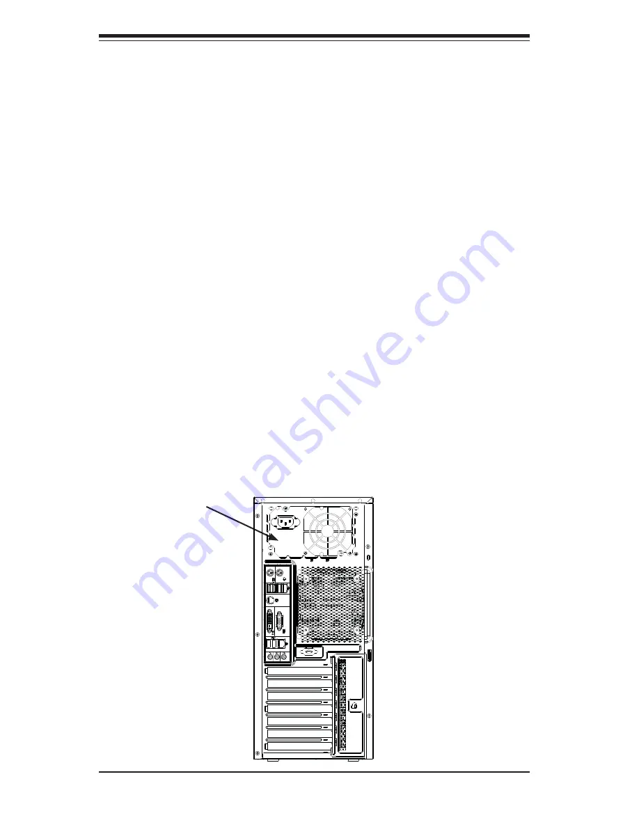
2.  Remove the screws securing the power supply to the chassis, which are 

located on the rear of the chassis. Set these screws aside for later use.

3.  Gently lift the power supply out of the chassis.

4.  Replace the failed power supply with an identical power supply model.

5.  Secure the new power supply using the screws previously set aside.

6.  Plug the AC power cord back into the module and reconnect the motherboard 

cables.

7.  Power-up the system.

Figure 6-9.  Removing the Power Supply

Power Supply

Summary of Contents for Supero SuperServer 5037C-T

Page 1: ...SUPER SuperServer 5037C T USER S MANUAL Revision 1 0...

Page 2: ...ny such disputes Super Micro s total liability for all claims will not exceed the price paid for the hardware product FCC Statement This equipment has been tested and found to comply with the limits f...

Page 3: ...ribes the steps necessary to setup the system If your server was ordered without the processor and memory components this chapter will refer you to the appropriate sections of the manual for their ins...

Page 4: ...ow the procedures given in this chapter when installing removing or reconfigur ing Serial ATA or peripheral drives and when replacing system power supply units and cooling fans Chapter 7 BIOS The BIOS...

Page 5: ...v Preface Notes...

Page 6: ...2 2 Unpacking the System 2 1 2 3 System Access 2 2 Chapter 3 System Interface 3 1 Overview 3 1 3 2 Control Panel Button 3 1 3 3 Control Panel LEDs 3 1 Chapter 4 System Safety 4 1 Electrical Safety Pr...

Page 7: ...Installing Drivers 5 25 SuperDoctor III 5 26 Chapter 6 Advanced Chassis Setup 6 1 Static Sensitive Devices 6 1 6 2 Rotating the Hard Drive Cage 6 2 6 3 Removing and Installing Hard Drives 6 3 6 4 Remo...

Page 8: ...viii SUPERSERVER 5037C T User s Manual Notes...

Page 9: ...ed for use with the SuperServer 5037C T www supermicro com In addition to the motherboard and chassis various hardware components have been included with the SuperServer 5037C T as listed below One 12...

Page 10: ...ry Please refer to Chapter 5 for installing memory Serial ATA An on chip SATA controller is integrated into the X9SCA to provide a six port SATA subsystem which is RAID 0 1 5 and 10 supported RAID 5 s...

Page 11: ...support four SATA hard drives these drives are not hot swappable Front Control Panel The control panel provides you with system monitoring and control LEDs indicate power network activity hard disk dr...

Page 12: ...PCIe_x4 PCIe x8 SLOT 4 SATA PORTS SATA II 300MB s 8 USB PORTS USB2 0 480Mbps FLASH SPI 32Mb SPI PCIe_x1 2 5Gbps GLAN1 82574L COM1 2 P S2 LPC HEALTH INFO P11 12 P13 16 LPC TPM1 2 Header P9 10 LPC PCIe_...

Page 13: ...dress Super Micro Computer B V Het Sterrenbeeld 28 5215 ML s Hertogenbosch The Netherlands Tel 31 0 73 6400390 Fax 31 0 73 6416525 Email sales supermicro nl General Information support supermicro nl T...

Page 14: ...1 6 SUPERSERVER 5037C T User s Manual Notes...

Page 15: ...erver itself shows damage you should file a damage claim with the carrier who delivered it Decide on a suitable location for setting up and operating the SuperServer 5037C T It should be situated in a...

Page 16: ...w Cooling air is provided by the chassis fan and the power supply fan The system component layout was carefully designed to promote sufficient airflow throughout the chassis Also note that all power a...

Page 17: ...Chapter 2 System Setup 2 3 Figure 2 1 Accessing the Inside of the System 1 3 1 6 2 2 1 5...

Page 18: ...2 4 SUPERSERVER 5037C T User s Manual Notes...

Page 19: ...om the power supply to the server system When power is on this button will be illuminated by a blue LED Turning off system power with this button removes the main power but keeps standby power supplie...

Page 20: ...ously on and not flashing it indicates an overheat condition which may be caused by cables obstructing the airflow in the system or the ambient room temperature being too warm Check the routing of the...

Page 21: ...ith the operating system first and then unplug the power cords of all the power supply units in the system When working around exposed electrical circuits another person who is familiar with the power...

Page 22: ...your body which are excellent metal conductors that can create short circuits and harm you if they come into contact with printed circuit boards or areas where power is present Serverboard Battery CA...

Page 23: ...use Touch a grounded metal object before removing the board from the antistatic bag Do not let components or PCBs come into contact with your clothing which may retain a charge even if you are wearing...

Page 24: ...y in the garbage or a public landfill Please comply with the regulations set up by your local hazardous waste management agency to dispose of your used battery properly 4 4 Operating Precautions Care...

Page 25: ...t the size and weight of the motherboard can cause it to bend if handled improperly which may result in damage To prevent the motherboard from bending keep one hand under the center of the board to su...

Page 26: ...sink only Make sure to install the serverboard into the chassis before you install the CPU heatsinks When receiving a serverboard without a processor pre installed make sure that the plastic CPU socke...

Page 27: ...CPU horizontally or vertically Do not rub the CPU against the surface or against any pins of the socket to avoid damage to the CPU or the socket With the CPU inside the socket inspect the four corner...

Page 28: ...r locked into place Warning The CPU will only seat inside the socket in one direction Make sure it is properly inserted before closing the load plate If it doesn t close properly do not force it as it...

Page 29: ...th other compo nents 3 Inspect the CPU Fan wires to make sure that the wires are routed through the bottom of the heatsink 4 Remove the thin layer of the protec tive film from the copper core of the h...

Page 30: ...g holes until you hear a click Also make sure to orient each fastener so that the narrow end of the groove is pointing outward 2 Repeat Step 7 to insert all four heatsink fasteners into the mounting h...

Page 31: ...nd to prevent damage done to the CPU or other components Active Heatsink Removal 1 Unplug the power cord from the power supply 2 Disconnect the heatsink fan wires from the CPU fan header 3 Use your fi...

Page 32: ...ta cables with their motherboard connector locations noted should be connected See the motherboard layout diagram in this chapter for connector locations DVD ROM Drive cable SATA0 Control Panel cable...

Page 33: ...ection in this chapter for details and pin descrip tions of JF1 5 4 I O Ports The I O ports are color coded in conformance with the PC 99 specification See Figure 5 2 below for the colors and location...

Page 34: ...snaps into place in the slot Repeat fstep 1 to install to DIMM1B if needed Memory Support The X9SCA supports up to 32GB of ECC unbuffered UDIMM DDR3 1333 1066 memory in four memory slots Populating th...

Page 35: ...ity System Device Size Physical Memory Remaining Available 4 GB Total System Memory Firmware Hub flash memory System BIOS 1 MB 3 99 Local APIC 4 KB 3 99 Area Reserved for the chipset 2 MB 3 99 I O API...

Page 36: ...and its bracket into the slot on the chassis and insert the expansion card into its slot on the motherboard 6 If desired screws can be used to secure the expansion card into the chassis 7 Close the p...

Page 37: ...2 JI2C2 JI2C1 JI2C1 SLOT1 SLOT1 SLOT2 SLOT2 SLOT4 SLOT4 SLOT3 SLOT3 SLOT5 SLOT5 SLOT6 SLOT6 B1 B1 FAN4 FAN4 JBT1 JBT1 CPU CPU DIMM1A DIMM1A DIMM2A DIMM2A DIMM1B DIMM1B DIMM2B DIMM2B 0 1 0 1 Jumper Des...

Page 38: ...3Mb s JPI2 C PWR supply I2 C System Management Bus JSPK Speaker Header Pins 3 4 Internal 1 4 External JTPM Trusted Platform Module TPM Header JWF1 SATA DOM Disk On Module Power Connector JWOL Wake On...

Page 39: ...ll VRMs See the table on the right for pin definitions ATX Power 24 pin Connector Pin Definitions JPW1 Pin Definition Pin Definition 13 3 3V 1 3 3V 14 12V 2 3 3V 15 COM 3 COM 16 PS_ON 4 5V 17 COM 5 CO...

Page 40: ...lure Refer to the table on the right for pin definitions OH Fan Fail LED Pin Definitions JF1 Pin Definition 7 Vcc Blue UID LED 8 OH Fan Fail LED OH Fan Fail Indicator Status State Definition Off Norma...

Page 41: ...13 Pin Definition 1 5V 6 5V 2 USB_PN2 7 USB_PN3 3 USB_PP2 8 USB_PP3 4 Ground 9 Ground 5 No Con nection 10 Key Serial Ports The COM1 Port is located on the I O backpanel COM2 is a header located on th...

Page 42: ...at JL1 on the motherboard Attach the ap propriate cable from the chassis to inform you of a chassis intrusion when the chas sis is opened ATX PS 2 Keyboard and PS 2 Mouse Ports The ATX PS 2 keyboard...

Page 43: ...1 Trusted Platform Module Header This header is used to connect a Trusted Platform Module TPM available sepa rately from a third party vendor A TPM is a security device that allows encryption and auth...

Page 44: ...e management chip in the system See the table on the right for pin definitions Refer to the board layout below for the locations of the headers Wake On LAN JWOL The Wake On LAN header is located at JW...

Page 45: ...clear CMOS and will also clear any passwords Instead of pins this jumper consists of contact pads to prevent accidentally clearing the contents of CMOS To Clear CMOS 1 First power down the system and...

Page 46: ...Pin Definition 1 2 Enabled Default 2 3 Disabled PCI Slot SMB Enable Disable Jumper Settings Jumper Setting Definition Closed Enabled Open Default Disabled PCI Slot SMB Enable Use jumpers JI2 C1 JI2 C...

Page 47: ...oard This LED will be on when the system is running Unsupported Memory LED LE3 LE3 is located next to LE2 When LE3 blinks it is an indication warning that unsupported memory is installed in one or mor...

Page 48: ...I SATA 0 5 are located on the motherboard See the table on the right for pin definitions for the onboard SATA ports The SATA0 1 ports support SATA3 6 Gb s while ports 2 through 5 support SATA2 3 Gb s...

Page 49: ...omputer icon and then on the icon representing your CD ROM drive Finally double click on the S Setup icon Figure 5 4 Driver Installation Display Screen Click the icons showing a hand writing on paper...

Page 50: ...ucial system information such as CPU temperature system voltages and fan status See the Figure below for a display of the SuperDoctor III interface Note The default User Name and Password for SuperDoc...

Page 51: ...ctor III program and User s Manual can be downloaded from the Supermicro web site at http www supermicro com products accessories software SuperDoctorIII cfm For Linux we recommend using SuperDoctor I...

Page 52: ...5 28 SUPERSERVER 5037C T User s Manual Notes...

Page 53: ...owing measures are generally sufficient to protect your equipment from static discharge Precautions Use a grounded wrist strap designed to prevent static discharge Touch a grounded metal object before...

Page 54: ...nt room to install and configure the chassis components The side chassis panels must be removed to access the inside of the chassis refer to Chapter 2 for instructions on removing the panels Rotating...

Page 55: ...isconnect the system from any power source 2 Rotate the hard drive cage outward 90 degrees as described in the previous section 3 Disconnect all cables from the hard drive 4 Press the release tab on t...

Page 56: ...it the Supermicro Web site at http www supermicro com products nfo files storage SAS 1 CompList 110909 pdf 8 Insert the new hard drive into the hard drive carrier 9 Insert the hard drive carrier into...

Page 57: ...he SC732 chassis must be powered down before hard drives can be removed from the system Adding these drives is optional Removing and Installing 2 5 Hard Drives 1 Disconnect the chassis from any power...

Page 58: ...6 Remove the hard drive from the hard drive carrier 7 Insert the new hard drive into the hard drive carrier 8 Insert the hard drive carrier into the hard drive cage sliding it towards the back of the...

Page 59: ...f the front of the chassis 2 Remove the cover plate from the 3 5 device slot on the front of the chassis 3 Install the bracket rail A onto one side of the 3 5 device by inserting the pins of the brack...

Page 60: ...fails the system must be powered down before replacing it If the power supply fan fails the power supply itself must be replaced Replacing the System Fan 1 Power down the server and disconnect it fro...

Page 61: ...he mounting holes in the front fan 3 Pull the rubber pins through the mounting holes of the system fan to secure the fan to the chassis 4 Lower the fan into the chassis aligning the holes at the top o...

Page 62: ...ce Also disconnect all power cables that are connected to the motherboard 2 Remove the screws securing the power supply to the chassis which are located on the rear of the chassis Set these screws asi...

Page 63: ...two main frames The left frame displays all the options that can be configured Grayed out options cannot be configured Options in blue can be configured by the user The right frame displays the key le...

Page 64: ...e to update the BIOS do not shut down or reset the system while the BIOS is updating This is to avoid possible boot failure 7 2 Main Setup When you first enter the AMI BIOS Setup Utility you will ente...

Page 65: ...he arrow keys to move between fields The date must be entered in Day MM DD YY format The time is entered in HH MM SS format Note The time is in the 24 hour format For example 5 30 P M appears as 17 30...

Page 66: ...ait For F1 If Error This forces the system to wait until the F1 key is pressed if an error occurs The options are Disabled and Enabled Interrupt 19 Capture Interrupt 19 is the software interrupt that...

Page 67: ...f for the system power to remain off after a power loss Select Power On for the system power to be turned on after a power loss Select Last State to allow the system to resume its last state before a...

Page 68: ...d where it cannot thus preventing a worm or a virus from flooding illegal codes to overwhelm the processor or damage the system during an attack The default is Enabled Refer to Intel and Microsoft Web...

Page 69: ...umption limit in Watts during a long duration time window Long duration maintained this is the time in milliseconds where the Long Duration Power Limit is maintained Short duration power limit During...

Page 70: ...bled and Disabled PCIE Maximum Payload Size This feature selects the setting for the PCIE maximum payload size The options are Auto 128 Bytes 256 Bytes 512 Bytes 1024 Bytes 2048 Bytes and 4096 Bytes P...

Page 71: ...DE Devices and displays the following items SATA Mode This item selects the mode for the installed drives The options are Disabled IDE Mode AHCI Mode and RAID Mode IDE Mode The following items are dis...

Page 72: ...en RAID Mode is selected SATA Port0 Port5 This item displays the information detected on the installed SATA drives on the particular SATA port Hot Plug Set this item to Enabled to enable hot plugging...

Page 73: ...isabled Serial Port1 Settings Serial Port2 Settings This option specifies the base I O port address and the Interrupt Request address of Serial Port 1 and Serial Port 2 Select Disabled to prevent the...

Page 74: ...L COM4 Terminal Type Select ANSI VT100 VT100 or VT UTF8 Bits per Second BPS 9600 19200 57600 or 115200 Data Bits 8 or 7 Parity None Even Odd Mark or Space Stop Bits 1 or 2 Hardware Health Configuratio...

Page 75: ...tionary level and generally means that there may be factors contributing to this condition but the CPU is still within its normal operating state and below the CPU Temperature Tolerance The motherboar...

Page 76: ...ing allows you to configure the ACPI Advanced Configuration and Power Interface sleep state for your system when it is in the Suspend mode The options are Suspend Disabled and S1 POS NUMA Support This...

Page 77: ...he IPMI specifications please visit Intel s website at www intel com BMC Support This feature enables or disables the installed Baseboard Management Controller BMC on the motherboard The options are E...

Page 78: ...EL Full This option automatically clears the System Event Log memory of all messages when it is full The options are Do Nothing and Erase Immediately Log EFI Status Codes This option enables or disabl...

Page 79: ...wing items are displayed when Static is selected Station IP Address Enter the IP address for this machine This should be in decimal and in dotted quad form i e 192 168 10 253 The value of each three d...

Page 80: ...ture allows the user to delete a previously defined boot device from which the systems boots from during startup Boot Option 1 Boot option 2 Boot Option 3 etc The settings are Built in EFI Shell and a...

Page 81: ...command or attempts to write to the boot sector of the hard disk drive The options are Enabled and Disabled BIOS SETUP UTILTY Main Advanced Security Boot Exit Select Screen Select Item Enter Select C...

Page 82: ...Exit from the Exit menu and press Enter Discard Changes Select this option and press Enter to discard all the changes and return to the AMI BIOS Utility Program Restore Defaults To set this feature se...

Page 83: ...ave any changes to the BIOS setup for future use Restore User Defaults To set this feature select Restore User Defaults from the Exit menu and press En ter Use this feature to retrieve user defined se...

Page 84: ...4 22 SUPERSERVER 5037C T User s Manual Notes...

Page 85: ...rror oc curs you should consult with your system manufacturer for possible repairs These fatal errors are usually communicated through a series of audible beeps The numbers on the fatal error list cor...

Page 86: ...A 2 SUPERSERVER 5037C T User s Manual Notes...

Page 87: ...to 32 GB of unbuffered DDR3 1333 1066 memory See the memory section in Chapter 5 for details SATA Controller Intel on chip controller for six port SATA RAID 0 1 5 and 10 supported RAID 5 not supporte...

Page 88: ...dity 8 to 90 non condensing Non operating Relative Humidity 5 to 95 non condensing Regulatory Compliance Electromagnetic Emissions FCC Class A EN 55022 Class A EN 61000 3 2 3 3 CISPR 22 Class A Electr...

Page 89: ...B 3 Appendix B System Specifications Notes...

Page 90: ...form be reasonably expected to result in significant injury or loss of life or catastrophic property damage Accordingly Supermicro dis claims any and all liability and should buyer use or sell such pr...

Reviews: