background image

Chapter 4: AMI BIOS

4-21

The settings are 1st Floppy Drive and Disabled. The default settings are the fol-
lowing:

1st Boot Device – 1st Floppy Drive

• 

2nd Boot Device - SATA

• 

Hard Disk Drives

This feature allows the user to specify the boot sequence from available Hard Disk 
Drives.

1st Drive - SATA

• 

Removable Drives

This feature allows the user to specify the boot sequence from available Remov-
able Drives.

1st Drive

• 

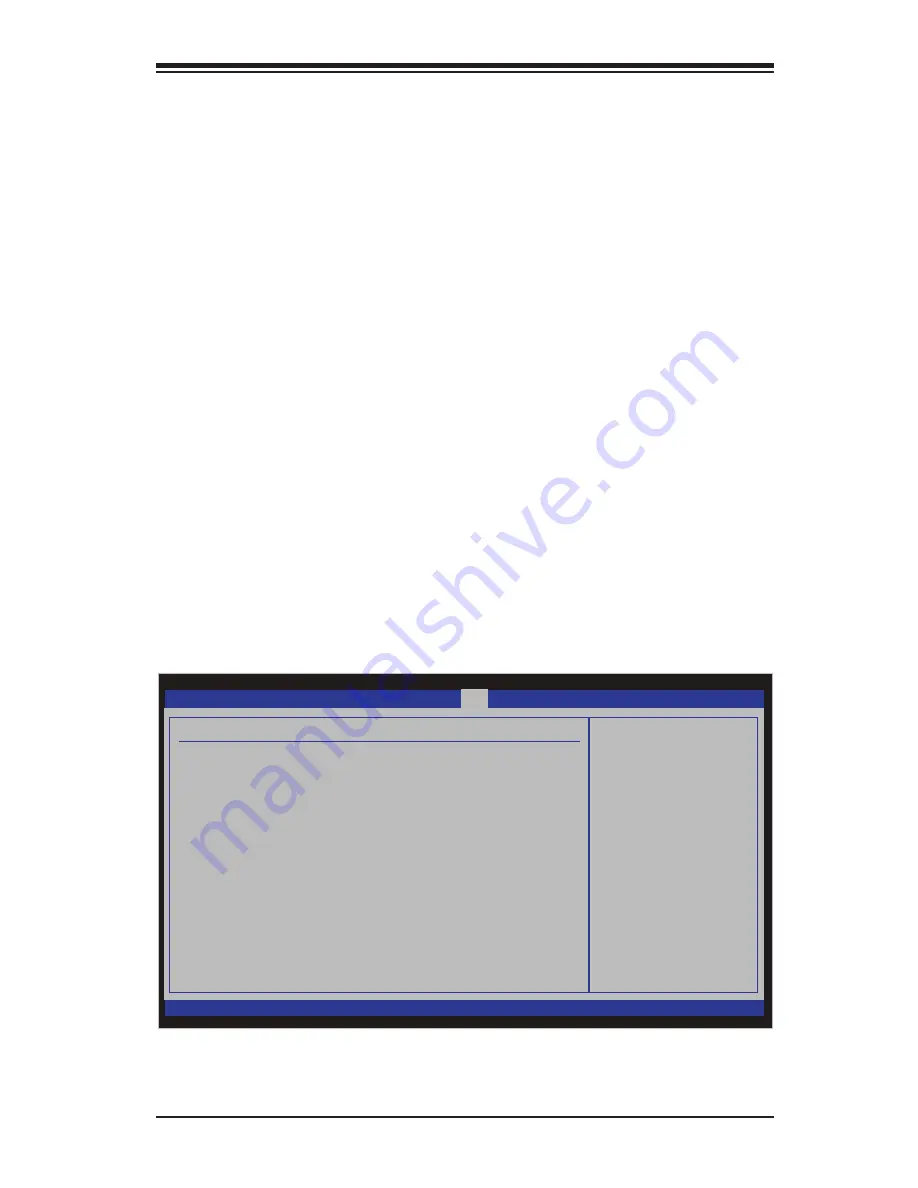
4-6  Exit Options

Select the Exit tab from the AMI BIOS Setup Utility screen to enter the Exit BIOS 
Setup screen.

BIOS SETUP UTILTY

Main

Advanced

Security

Boot

Exit

vXX.XX (C) Copyright 1985-2009, American Megatrends, Inc.

Exit Options

Save Changes and Exit

Discard Changes and Exit
Discard Changes

Load Optimal Defaults
Load Failsafe Defaults

Exit system setup
after saving the
changes.

F10 key can be used
for this operation.




Select Screen

 


Select Item

+-    

Change Field

Tab  

Select Field

F1   

General Help

F10  

Save and Exit

ESC  

Exit

Summary of Contents for Supero C2G41

Page 1: ...C2G41 USER S MANUAL Revision 1 0...

Page 2: ...R DATA Any disputes arising between manufacturer and customer shall be governed by the laws of Santa Clara County in the State of California USA The State of California County of Santa Clara shall be...

Page 3: ...nded to be professionally installed and serviced by a techni cian Manual Organization Chapter 1 describes the features specifications and performance of the mainboard and provides detailed information...

Page 4: ...ACPI Features 1 10 1 6 Power Supply 1 11 1 7 Versatile Media Capabilities 1 11 1 8 Super I O 1 12 Chapter 2 Installation 2 1 Electro Static Sensitive Devices 2 1 2 2 Motherboard Installation 2 2 2 3 P...

Page 5: ...2 Clear CMOS 2 32 2 8 Onboard Indicators 2 33 GLAN LED Indicators 2 33 Onboard Power LED 2 34 2 9 Hard Drive Connections 2 35 IDE Disk Drive Connector 2 35 SATA Disk Drive Connectors 2 36 Chapter 3 Tr...

Page 6: ...ngs 4 19 4 5 Boot Configuration 4 20 4 6 Exit Options 4 21 Appendices Appendix A BIOS POST Messages A 1 Appendix B Installing the Microsoft Windows OS B 1 Appendix C Software Driver Installation Instr...

Page 7: ...ail to provide you with the highest standards in quality and performance Please check that the following items have all been included with your mother board If anything listed here is damaged or missi...

Page 8: ...er Micro Computer B V Het Sterrenbeeld 28 5215 ML s Hertogenbosch The Netherlands Tel 31 0 73 6400390 Fax 31 0 73 6416525 Email sales supermicro nl General Information support supermicro nl Technical...

Page 9: ...ictures and drawings shown in this manual were based upon the latest PCB Revision available at the time of publishing of the manual The motherboard you ve received may or may not look exactly the same...

Page 10: ...121 JPT1 C2G41 Tested to Comply With FCC Standards FOR HOME OR OFFICE USE ATX_POWER1 LGA775 CPU ATX12V1 COM2 COM1 1 A JL1 CHASSIS INTRUSION TPM IDE HDMI JF1 X PWR ON RST OH FF X HDD NIC1 LED PWR LED...

Page 11: ...ort IDE IDE Connector JF1 FP Control Panel Header JL1 Chassis Intrusion Header JWOL Wake on LAN Header BUZZER Internal Buzzer Speaker AUDO FP Front Panel Audio Header Connector KB MOUSE PS 2 Keyboard...

Page 12: ...CI Express x1 Two 2 32 bit PCI 33MHz BIOS 8 Mb Firmware AMI BIOS Flash BIOS Plug and Play PnP APM 1 2 PCI 2 2 ACPI 1 0 2 0 USB Keyboard Support PC Health Monitoring Onboard voltage monitors for CPU co...

Page 13: ...100 1000 Ethernet port Realtek RTL8111C VC GR Security Trusted Platform Module TPM 1 2 support Serial USB Keyboard and Mouse Two 2 16550 Fast UART serial headers on board One 1 PS 2 mouse and One 1 ke...

Page 14: ...33MHz GMCH ITE 8720F J PCIE x1 VGA PCIE x16 BW 2GB s DIMM1A DDR3 Socket 240P Super I O INTEL USB V2 0 DIMM1B DDR3 Socket 240P PCI Slot 120pin AD17 REALTEK port 0 7 USB x8 BW 10GB s BW 500MB s Freq 100...

Page 15: ...ory Access Dual Channel DDR3 Memory Intel Flex Memory Technology Intel Clear Video Technology HDMI Interface Intel High Definition Audio Intel ICH7 System Features The I O Controller ICH7 provides the...

Page 16: ...voltage monitor by using SuperO Doctor III 1 5 ACPI Features ACPI stands for Advanced Configuration and Power Interface The ACPI specifica tion defines a flexible and abstract hardware interface that...

Page 17: ...equired by the CPU some are inadequate A 2 Amp of current supply on a 5V Standby rail is strongly recom mended It is strongly recommended that you use a high quality power supply that meets 12V ATX po...

Page 18: ...O and provides two high speed 16550 compatible serial communication ports UARTs Each UART includes a 16 byte send receive FIFO a programmable baud rate generator complete modem control capability and...

Page 19: ...y do not touch its components peripheral chips memory modules or gold contacts When handling chips or modules avoid touching their pins Put the motherboard and peripherals back into their antistatic b...

Page 20: ...herboard and chassis match Although a chassis may have both plastic and metal mounting fas teners metal ones are highly recommended because they ground the motherboard to the chassis Make sure that th...

Page 21: ...as needed Align the mounting holes on the motherboard against the mounting holes on the chassis Install the motherboard into the chassis carefully to avoid damage to mother board components Insert a...

Page 22: ...the CPU fan and heatsink assembly If you buy a CPU separately make sure that you use only Intel certified multi directional heatsink and fan 3 Make sure to install the motherboard into the chassis bef...

Page 23: ...socket key the Notch on the same side of the triangle cutout on the socket Once aligned carefully lower the CPU straight down to the socket Do not drop the CPU on the socket Do not move the CPU horizo...

Page 24: ...t as it may damage your CPU Instead open the load plate again and double check that the CPU is aligned properly Do not rub the CPU against the surface or against any pins of the socket to avoid damage...

Page 25: ...lly released from the load plate when the load lever is pushed in the lever lock Remove the PnP cap from the motherboard 6 CPU properly installed Load lever locked into place Important Please save the...

Page 26: ...atsink Remove the thin layer of the pro tective film from the copper core of the heatsink Warning CPU may overheat if the protective film is not removed from the heatsink Apply the proper amount of th...

Page 27: ...ntil you hear a click Note Make sure to orient each fastener so that the narrow end of the groove is pointing outward Repeat Step 7 to insert all four heat sink fasteners into the mounting holes 7 8 9...

Page 28: ...e fastener upward to loosen it Repeat Step 3 to loosen all fasteners from the mounting holes With all fasteners loosened remove the heatsink from the CPU Active Heatsink Removal Removing the Heatsink...

Page 29: ...stallation by fully tightening all four screws Screw in two diagonal screws i e the 1 and the 2 screws until just snug do not over tighten the screws to avoid possible damage to the CPU Place the heat...

Page 30: ...as shown in the illustration below Loosen screws in se quence as shown Screw 2 Motherboard Remove the Heatsink Bracket from under neath the mother board Screw 1 Screw 3 Screw 4 1 2 3 4 Clean the surf...

Page 31: ...memory modules CAUTION Exercise extreme care when installing or removing DIMM modules to prevent any possible damage DIMM Installation Insert the desired number of DIMMs into the memory slots startin...

Page 32: ...DDR3 Slot Position the DIMM module s bottom key so it aligns with the receptive point on the slot When the module is properlly inserted the Lock Release tabs will automatically secure the DIMM module...

Page 33: ...es driver compatibility For more information please read the following article at Microsoft s Knowledge Base website at http support microsoft com kb 888137 Possible System Memory Allocation Availabil...

Page 34: ...ATTERY JPW2 JPW1 AUDIO FP USB0 1 USB2 3 DIMM1B DIMM1A SLOT7 PCI E X16 SLOT6 PCI E X1 SLOT5 PCI 33MHZ SLOT4 PCI 33MHZ USB6 7 LAN USB4 5 SPDIF OUT KB MOUSE CMOS CLEAR ENABLE JPT1 1 2 2 3 DISABLE VGA PSK...

Page 35: ...USB Ports attach USB devices to these ports as needed such as mice memory card readers etc USB Port 5 USB Port 4 USB Port 6 USB Port 7 Gigabit LAN connect to a network using an RJ45 type cable connec...

Page 36: ...ins Power Button OH Fan Fail LED 1 NIC1 LED Reset Button 2 HDD LED Power LED Reset PWR LED_Anode LED_Anode LED_Anode LED_Anode Ground Ground X X X X FAN2 FAN1 LE1 JBT1 JF1 121 JPT1 C2G41 Tested to Com...

Page 37: ...A PSKBM AUDIO Power LED The Power LED connection is located on pins 15 and 16 of JF1 Refer to the table on the right for pin definitions Power LED Pin Definitions JF1 Pin Definition 15 LED_Anode 16 PW...

Page 38: ...located on pins 11 and 12 of JF1 Attach the NIC LED cables to display network activity Refer to the table on the right for pin definitions GLAN 1 LED Pin Definitions JF1 Pin Definition 11 LED_Anode 12...

Page 39: ...ach it to a hardware reset switch on the computer case Refer to the table on the right for pin definitions Reset Button Pin Definitions JF1 Pin Definition 3 Reset 4 Ground A Reset B PWR Button Power B...

Page 40: ...Power Connector A 4 pin 12V power connector is located at JPW2 on the motherboard This power connector also meets the SSI EPS 12V specification and is required to ensure adequate power to the pro ces...

Page 41: ...l USB Ports 6 7 C Front Panel USB 0 1 Back Panel USB 0 5 Pin Definitions 1 5V 2 PO 3 PO 4 Ground 5 N A Front Panel USB 6 7 8 9 and Front Ac cessible Onboard USB 10 Connections Pin Definition Pin Defin...

Page 42: ...on the motherboard Fan Header Pin Definitions Fan1 3 Pin Definition 1 Ground 2 12V 3 Tachometer 4 PWR Modulation A B C A Fan 1 CPU Fan B Fan 2 C Fan 3 A B C Overheat LED Pin Definitions Pin Definition...

Page 43: ...CLEAR ENABLE JPT1 1 2 2 3 DISABLE VGA PSKBM AUDIO ATX PS 2 Keyboard and PS 2 Mouse Ports The ATX PS 2 keyboard and the PS 2 mouse are located at J8 See the table on the right for pin definitions The...

Page 44: ...und 3 Wake up A A FAN2 FAN1 LE1 JBT1 JF1 121 JPT1 C2G41 Tested to Comply With FCC Standards FOR HOME OR OFFICE USE ATX_POWER1 LGA775 CPU ATX12V1 COM2 COM1 1 A JL1 CHASSIS INTRUSION TPM IDE HDMI JF1 X...

Page 45: ...I SATA1 I SATA0 BUZZER JWOL BATTERY JPW2 JPW1 AUDIO FP USB0 1 USB2 3 DIMM1B DIMM1A SLOT7 PCI E X16 SLOT6 PCI E X1 SLOT5 PCI 33MHZ SLOT4 PCI 33MHZ USB6 7 LAN USB4 5 SPDIF OUT KB MOUSE CMOS CLEAR ENABL...

Page 46: ...nd is then output through the Line In Line Out and MIC jacks See at the picture at right Grey Side Surround Black Back Surround Orange CEN LFE Pink Mic In Green Front Blue Line In FAN2 FAN1 LE1 JBT1 J...

Page 47: ...s talk See the table below for pin definitions High Definition Fron Panel Audio Pin Signal 1 MC_L 2 AUD_GND 3 MC_R 4 FP_Audio Detect 5 Line_2_R 6 SENSE1_RETURN 7 AUD_GND 8 Key 9 Line_2_L 10 SENSE2_RET...

Page 48: ...y both high definition video and digital sound through an HDMI capable display using just a single HDMI cable B B FAN2 FAN1 LE1 JBT1 JF1 121 JPT1 C2G41 Tested to Comply With FCC Standards FOR HOME OR...

Page 49: ...choose between optional settings Jumpers create shorts between two pins to change the function of the connector Pin 1 is identified with a square solder pad on the printed circuit board See the mothe...

Page 50: ...MOS Instead of pins this jumper consists of contact pads to prevent the accidental clearing of CMOS To clear CMOS use a metal object such as a small screwdriver to touch both pads at the same time to...

Page 51: ...LAN USB4 5 SPDIF OUT KB MOUSE CMOS CLEAR ENABLE JPT1 1 2 2 3 DISABLE VGA PSKBM AUDIO GLAN LEDs There is one Gigabit LAN port This Giga bit Ethernet LAN port has two LEDs The yellow LED indicates activ...

Page 52: ...16 SLOT6 PCI E X1 SLOT5 PCI 33MHZ SLOT4 PCI 33MHZ USB6 7 LAN USB4 5 SPDIF OUT KB MOUSE CMOS CLEAR ENABLE JPT1 1 2 2 3 DISABLE VGA PSKBM AUDIO A Power LED Onboard PWR LED Indicator LE1 LED Color Defini...

Page 53: ...wire typically designates the location of pin 1 IDE Disk Drive Connector ThereisoneIDEDiskDriveConnector on the C2G41 that can support up to two IDE devices Please refer to the jumper section for more...

Page 54: ...tions Pin Signal 1 Ground 2 SATA_TXP 3 SATA_TXN 4 Ground 5 SATA_RXN 6 SATA_RXP 7 Ground B A C D I SATA0 I SATA1 I SATA2 I SATA3 B A C D FAN2 FAN1 LE1 JBT1 JF1 121 JPT1 C2G41 Tested to Comply With FCC...

Page 55: ...tsink making sure it is fully seated and connect the chassis speaker and the power LED to the motherboard Check all jumper settings as well 5 Use the correct type of onboard CMOS battery as specified...

Page 56: ...ion 1 6 for details on recommended power supplies 2 The battery on your motherboard may be old Check to verify that it still supplies 3VDC If it does not replace it with a new one 3 If the above steps...

Page 57: ...Answer Microsoft implemented a design change in Windows XP with Service Pack 2 SP2 and Windows Vista This change is specific to the Physical Ad dress Extension PAE mode behavior which improves driver...

Page 58: ...then reboot Note The SPI BIOS chip installed on this motherboard is not removable To repair or replace a damaged BIOS chip please send your motherboard to RMA at Supermicro for service Question I thi...

Page 59: ...r disk drive for details on actual jumper locations and settings 3 4 Returning Merchandise for Service A receipt or copy of your invoice marked with the date of purchase is required be fore any warran...

Page 60: ...3 6 C2G41 User s Manual Notes...

Page 61: ...ot be configured Options in blue can be configured by the user The right frame displays the key legend Above the key legend is an area reserved for a text message When an option is selected in the lef...

Page 62: ...Setup screen is shown below System Overview The following BIOS information will be displayed System Time System Date Use this option to change the system time and date Highlight System Time or Sys te...

Page 63: ...2G41 This feature displays the version numbers and ID of the motherboard Version Build Date ID Processor The AMI BIOS will automatically display the status of processors as shown be low Processor Spee...

Page 64: ...t The options are Enabled and Disabled QuietBoot This option allows the bootup screen options to be modified between POST mes sages or the OEM logo Select Disabled to allow the computer system to disp...

Page 65: ...and Disabled USB Device Wake Up Select Enable to wake up the system via a USB device when the system is in S3 Standby or S4 Hibernate State The options are Enabled and Disabled PS 2 KB MS Wake Up Thi...

Page 66: ...tem to go to power saving mode while maintaining wake up capabilities The options are Enabled and Disabled Processor Clock Options Hardware Prefetcher Available when supported by the OS and the CPU If...

Page 67: ...r s Platform Environment Control Interface PECI feature PECI uses the processor s Digital Thermal Sensor DTS to man age thermal conditions Please see the item CPU Overheat Alarm under Hard ware Health...

Page 68: ...This feature allows the user to select the DRAM Frequency setting The options are Auto Auto detect 800 MHz and 1067 MHz Configure DRAM Timing by SPD Select Enable to allow the BIOS to read the SPD Ser...

Page 69: ...the BIOS Video Function Configuration DVMT Mode Select Select DVMT Mode to enable Dynamic Video Memory Technology DVMT mode which dynamically allocates video memory for optimal efficiency on 2D 3D vi...

Page 70: ...to configure USB settings for the motherboard Legacy USB Support Select Enabled to use Legacy USB devices If this item is set to Auto Legacy USB support will be automatically enabled if a legacy USB...

Page 71: ...stalled in the system The options are 0 sec 5 10 15 20 25 30 and 35 Primary IDE Master Slave Secondary IDE Master Slave Third IDE Master Slave Third IDE is available only when Enhanced is selected und...

Page 72: ...s a data transfer rate of 16 6 MBs This setting generally works with all hard disk drives manufactured after 1999 For other disk drives such as IDE CD ROM drives check the specifications of the drive...

Page 73: ...CI PnP configurations for the following items Clear NVRAM Select Yes to clear NVRAM during system boot The options are No and Yes Plug Play OS Select Yes to allow the OS to configure Plug Play devices...

Page 74: ...select the address to use as its I O port address The options are Disabled 3F8 IRQ4 3E8 IRQ4 and 2E8 IRQ3 For Serial Port2 select the address to use as its I O port address The options are Disabled 2...

Page 75: ...ention No action required Medium The processor is running warmer This is a precautionary level and generally means that there may be factors contributing to this condition but the CPU is still within...

Page 76: ...its Temperature Toler ance to the motherboard resulting in better CPU thermal management Supermicro has leveraged this feature by assigning a temperature status to certain thermal conditions in the pr...

Page 77: ...ay Serial Port Number This feature allows the user decide which serial port to be used for Console Redirection The options are COM 1 and COM 2 Serial Port Mode This feature allows the user to set the...

Page 78: ...mputing TCG TPM Support Select Yes to enable support for trusted platforms TPM 1 2 and allow the BIOS to automatically download the drivers needed to provide support for the platforms specified The op...

Page 79: ...ailable when Supervisor Password is set as above Available options are Full Access grants full User read and write access to the Setup Utility View Only allows access to the Setup Utility but the fiel...

Page 80: ...the Security Setup screen When Enabled the AMI BIOS displays a warning when any program or virus issues a Disk Format command or attempts to write to the boot sector of the hard disk drive The options...

Page 81: ...from available Remov able Drives 1st Drive 4 6 Exit Options Select the Exit tab from the AMI BIOS Setup Utility screen to enter the Exit BIOS Setup screen BIOS SETUP UTILTY Main Advanced Security Boo...

Page 82: ...xit from the Exit menu and press Enter Discard Changes Select this option and press Enter to discard all the changes and return to the AMI BIOS Utility Program Load Optimal Defaults To set this featur...

Page 83: ...turer for possible repairs These fatal errors are usually communicated through a series of audible beeps The numbers on the fatal error list on the following page correspond to the num ber of beeps fo...

Page 84: ...A 2 C2G41 User s Manual Notes...

Page 85: ...tup will automati 5 cally load all Windows supplied device drivers and then continue with the Windows XP 2003 installation You will be asked to enter the disk partition where the Operating System is t...

Page 86: ...B 2 C2G41 User s Manual Notes...

Page 87: ...ng each item you must re boot the system before proceeding with the next item on the list The bottom icon with a CD on it allows you to view the entire contents of the CD Appendix C Software Installat...

Page 88: ...ys crucial system information such as CPU temperature system voltages and fan status See the Figure below for a display of the Supero Doctor III interface Note 1 Both default user name and password ar...

Page 89: ...e Control Note SD III Software Revision 1 0 can be downloaded from our Web site at ftp ftp supermicro com utility Supero_Doctor_III You can also download SDIII User s Guide at http www supermicro com...

Page 90: ...C 4 C2G41 User s Manual Notes...

Page 91: ...recovery process will only recognize COM1 Below is a two part procedure to recover the BIOS Part 1 Boot Sector Recovery Process 1 Using a different system download and copy the correct BIOS binary im...

Page 92: ...e except that the BIOS image file super rom is loaded from an IDE ATAPI CD DVD ROM RW disc drive that is attached to the system Note that loading from an IDE SATA hard disk drive is NOT supported 1 Us...

Page 93: ...ted to result in significant injury or loss of life or catastrophic property damage Accordingly Supermicro disclaims any and all liability and should buyer use or sell such products for use in such ul...

Reviews: