background image

Chapter 4: AMI BIOS

4-29

4-7   BIOS Recovery

Warning!

 Do not upgrade the BIOS unless your system has a BIOS-related 

issue. Flashing the wrong BIOS can cause irreparable damage to the 

system. In no event shall Supermicro be liable for direct, indirect, special, 

incidental, or consequential damages arising from a BIOS update. If you 

need to update the BIOS, do not shut down or reset the system while the 

BIOS is updating. This is to avoid possible boot failure. 

How to Recover the AMIBIOS Image (-the Main BIOS 
Block)

An AMIBIOS fl ash chip consists of a boot sector block, and a main BIOS code block 

(a main BIOS image). The boot sector block contains critical BIOS code, including 

memory detection and recovery code to be used to fl ash a new BIOS image if the 

original BIOS Image is corrupted. When the system is powered on, the boot sector 

code executes fi rst. Once it is completed, the main BIOS code will continue with 

system initialization and complete the bootup process. 

Notes: 

BIOS Recovery described below is used when the main BIOS 


block crashes. However, when the BIOS Boot sector crashes, you will need 

to send the motherboard back to Supermicro for RMA repairs.

4.7.1 Boot Sector Recovery from a USB Device

This feature allows the user to recover a BIOS image using a USB device without 

additional utilities needed. A user can download the BIOS image into a USB fl ash 

device, and name the fi le "SUPER.ROM" for the recovery process to load the fi le. 

A USB fl ash device such as a USB Flash Drive, a USB CDROM or a USB CDRW 

device can be used for this purpose, 

Insert the USB device that contains the new BIOS image (the ROM fi les) 

1. 

saved in a root directory into your USB drive.

While turning the power on, press and hold <Ctrl> and <Home> at the same 

2. 

time until the USB Access LED Indicator comes on. This might take a few 

seconds.

Once the USB drive LED is on, release the <Ctrl> and <Home> keys. 

3. 

AMIBIOS will issue beep codes to indicate that the BIOS ROM fi le is being 

updated.

When BIOS fl ashing is completed, the computer will reboot. Do not interrupt 

4. 

the fl ashing process until it is completed. 

Summary of Contents for Super X8DAH+

Page 1: ...USER S MANUAL Revision 1 0 X8DAH F X8DAH ...

Page 2: ...OR DATA Any disputes arising between manufacturer and customer shall be governed by the laws of Santa Clara County in the State of California USA The State of California County of Santa Clara shall be the exclusive venue for the resolution of any such disputes Super Micro s total liability for all claims will not exceed the price paid for the hardware product FCC Statement This equipment has been ...

Page 3: ...ced by professional technicians Manual Organization Chapter 1 describes the features specifications and performance of the mother board and provides detailed information about the chipset Chapter 2 provides hardware installation instructions Read this chapter when in stalling the processor memory modules and other hardware components into the system If you encounter any problems see Chapter 3 whic...

Page 4: ...formation given to ensure proper system installation or to prevent damage to the components Note Additional Information given to differentiate various models or to ensure correct system setup X8DAH X8DAH F User s Manual iv ...

Page 5: ...r Micro Computer B V Het Sterrenbeeld 28 5215 ML s Hertogenbosch The Netherlands Tel 31 0 73 6400390 Fax 31 0 73 6416525 Email sales supermicro nl General Information support supermicro nl Technical Support rma supermicro nl Customer Support Asia Pacific Address Super Micro Computer Inc 4F No 232 1 Liancheng Rd Chung Ho 235 Taipei County Taiwan R O C Tel 886 2 8226 3990 Fax 886 2 8226 3991 Website...

Page 6: ...Monitoring 1 11 Fan Status Monitor with Firmware Control 1 11 Environmental Temperature Control 1 11 System Resource Alert 1 12 1 6 ACPI Features 1 12 Slow Blinking LED for Suspend State Indicator 1 12 Main Switch Override Mechanism 1 12 1 7 Power Supply 1 13 1 8 Super I O 1 13 1 9 Overview of the Winbond WPCM450 Controller For X8DAH F Only 1 14 Chapter 2 Installation 1 2 1 Static Sensitive Device...

Page 7: ...Overheat OH Fan Fail LED 2 19 Power Fail LED 2 19 Reset Button 2 20 Power Button 2 20 2 6 Connecting Cables 2 21 Power Connectors 2 21 Fan Headers 2 22 Chassis Intrusion 2 22 Internal Speaker 2 23 Power LED Speaker 2 23 Overheat LED Fan Fail JOH1 2 24 System Management Bus 2 25 Power SMB I2 C Connector 2 25 2 7 Jumper Settings 2 26 Explanation of Jumpers 2 26 GLAN Enable Disable 2 26 CMOS Clear 2 ...

Page 8: ... 4 1 Starting the Setup Utility 4 2 4 2 Main Setup 4 2 4 3 Advanced Setup Configurations 4 4 4 4 Security Settings 4 24 4 5 Boot Configuration 4 25 4 6 Exit Options 4 27 4 7 BIOS Recovery 4 29 How to Recover the AMIBIOS Image the Main BIOS Block 4 29 4 7 1 Boot Sector Recovery from a USB Device 4 29 4 7 2 Boot Sector Recovery from an IDE CD ROM 4 30 4 7 3 Boot Sector Recovery from a Serial Port Se...

Page 9: ...s in quality and performance Check that the following items have all been included with your motherboard If anything listed here is damaged or missing contact your retailer The following items are included in the retail box One 1 Supermicro Mainboard One 1 floppy ribbon cable CBL 022L One 1 IDE ATA66 cable CBL 036L 03 Six 6 Serial ATA cables CBL 0044L One I O backpanel shield MCP 260 00025 0N One ...

Page 10: ...mage Note The drawings and pictures shown in this manual were based on the latest PCB Revision available at the time of publishing of the manual The motherboard you ve received may or may not look exactly the same as the graphics shown in the manual ...

Page 11: ... POPULATE SLOT0 FIRST Slot7 PCI E 2 0 x8 FAN3 FAN1 P2 DIMM1C P2 DIMM2C P2 DIMM2B P2 DIMM3B P2 DIMM1B P2 DIMM3C P2 DIMM2A P2 DIMM3A P2 DIMM1A P1 DIMM3C P1 DIMM2C P1 DIMM3B P1 DIMM2B P1 DIMM3A P1 DIMM2A P1 DIMM1C P1 DIMM1B P1 DIMM1A ALWAYS POPULATE DIMM1 FIRST CPU2 FAN FLOPPY IDE I SATA5 I SATA4 I SATA3 I SATA2 I SATA1 Slot6 PCI E 2 0 x16 Slot5 PCI E 2 0 x4 in x8 Slot Slot4 PCI E 2 0 x8 in x16 Slot ...

Page 12: ...O JPI1 JPG1 JWD1 JPT1 JPW2 JPW3 JPW1 SP1 FAN2 FAN6 FAN5 J14 JBAT1 JOH1 JL1 JI2C2 1 JI2C1 JD1 KB MS CD1 JIDE1 JWF1 USB 2 3 4 5 JUSB2 SMBUS1 ALWAYS POPULATE SLOT0 FIRST Slot7 PCI E 2 0 x8 FAN3 FAN1 P2 DIMM1C P2 DIMM2C P2 DIMM2B P2 DIMM3B P2 DIMM1B P2 DIMM3C P2 DIMM2A P2 DIMM3A P2 DIMM1A P1 DIMM3C P1 DIMM2C P1 DIMM3B P1 DIMM2B P1 DIMM3A P1 DIMM2A P1 DIMM1C P1 DIMM1B P1 DIMM1A ALWAYS POPULATE DIMM1 FI...

Page 13: ...aders Fans 7 8 CPU Fans 1 2 Floppy Floppy Drive IDE IDE Drive JD1 PWR LED Speaker Header Pins 1 3 Power LED Pins 6 7 Onboard Buzzer Pins 4 7 External Speaker JF1 Front Panel Connector JL1 Chassis Intrusion Header JOH1 Overheat LED Header JPI2 C Power Supply SMBbus I2 C Header JPW1 JPW2 JPW3 24 pin ATX PWR 8 pin Secondary PWR See Warning on Page 1 4 LAN1 2 Dedicated LAN G LAN RJ45 Ports Dedicated L...

Page 14: ...CI E 2 0 x4 in x8 slots Slot 5 One PCI E 2 0 x8 in x16 slots Slot 4 BIOS 32 Mb AMI SPI Flash ROM PCI 2 2 ACPI 1 0 2 0 3 0 Plug and Play PnP DMI 2 3 USB Keyboard sup port and SMBIOS 2 3 PC Health Monitoring Onboard voltage monitors for CPU0 Vcore CPU1 Vcore 1 5V 5V 5VSB 12V 12V 3 3Vcc 3 3VSB VBAT and Vtt Fan status monitor with firmware control CPU chassis temperature monitors Platform Environment ...

Page 15: ...ts and four Front Panel Front Accessible USB connections Super I O Winbond W83627DHG ALC 8830 Audio Controller supports 7 1 HD Audio with Line in Line out and Microphone Backpanel Audio and CD connections Two Internal1394 headers One EIDE Ultra DMA 100 bus master interface supports UDMA Mode 5 and PIO Mode 4 IPMI 2 0 with full KVM support X8DAH F only Note 2 Other Console redirection Onboard Fan S...

Page 16: ...DDR3 ESI X4 1 5 1 6 0 5 0 6 QPI QPI Slot 2 PCI E X8 Slot 1 Slot 4 PCI E X8 PCI E X16 PCI E X8 PCI E X8 QPI Slot 7 Slot 6 Slot 5 PCI E X4 PCI E X8 PCI E X8 PCI E X8 PCI E X16 PCI E X8 PCI E X16 PCI E X16 ESI Ports 7 8 Ports 9 10 Ports 3 4 Ports 5 6 Ports 7 10 IDE SIO LPC BUS FLOPPY 6 REAR 4 FRONT 6 FRONT LAN1 LAN2 SPI INTEL 82576 0 7 0 8 0 9 1 7 1 8 1 9 Ports 1 2 PCI 33MHZ HD AUDIO HDR1 HDR2 JVGA1 ...

Page 17: ... PCI E X16 ESI Ports7 8 Ports 9 10 Ports 3 4 Ports 5 6 Ports 7 10 IDE USB PCI 33MHZ SIO LPC BUS FLOPPY 6 REAR 4 FRONT 6 FRONT RMII LAN1 LAN2 SPI WPCM450 INTEL 82576 0 7 0 8 0 9 1 7 1 8 1 9 Ports 1 2 PCI 33MHz HD AUDIO HDR1 HDR2 JVGA1 JVGA1 JCOM2 KB RMII RTL 8201N LAN3 BMC MS BIOS CPU2 0 6 Intel ICH1OR Intel 5520 Intel 5520 X8DAH F Block Diagram IDE CTRL 1394 CTRL Audio CTRL X8DAH F System Diagram ...

Page 18: ...ing in addition to a differential forwarded clock A full width QPI link pair provides 84 signals The 5520 supports up to 36 PCI Express Gen2 lanes peer to peer read and write transactions The ICH10R provides up to seven PCI Express ports six SATA ports and 10 USB connections In addition the 5520 platform also offers a wide range of RAS Reliability Avail ability and Serviceability features These fe...

Page 19: ...he sensi tivity of the voltage monitor Fan Status Monitor with Firmware Control The PC health monitor can check the RPM status of the cooling fans The onboard CPU and chassis fans are controlled by Thermal Management via BIOS under Hardware Monitoring in the Advanced Setting Environmental Temperature Control The thermal control sensor monitors the CPU temperature in real time and will turn on the ...

Page 20: ...anism for Plug and Play and an operating system independent interface for configuration control ACPI leverages the Plug and Play BIOS data structures while providing a processor architecture independent implementation that is compatible with both Windows 2000 and Windows 2003 Operating Systems Slow Blinking LED for Suspend State Indicator When the CPU goes into a suspend state the chassis power LE...

Page 21: ...ally in areas where noisy power transmission is present you may choose to install a line filter to shield the computer from noise It is recommended that you also install a power surge protector to help avoid problems caused by power surges 1 8 Super I O The disk drive adapter functions of the Super I O chip include a floppy disk drive controller that is compatible with industry standard 82077 765 ...

Page 22: ...ection KVMR modules With blade oriented Super I O capability built in the WPCM450 Controller is ideal for legacy reduced server platforms The WPCM450 interfaces with the host system via a PCI interface to communicate with the Graphics core It supports USB 2 0 and 1 1 for remote keyboard mouse virtual media emulation It also provides LPC interface to control Super IO func tions The WPCM450 is conne...

Page 23: ...o not touch its components peripheral chips memory modules or gold contacts When handling chips or modules avoid touching their pins Put the motherboard and peripherals back into their antistatic bags when not in use For grounding purposes make sure your computer chassis provides excellent conductivity between the power supply the case the mounting fasteners and the motherboard Use only the correc...

Page 24: ...sis 1 Locate the mounting holes on the moth 2 erboard Refer to the layout above for mounting hole locations Locate the matching mounting holes on 3 the chassis Align the mounting holes on the motherboard against the mounting holes on the chassis 2 2 Motherboard Installation All motherboards have standard mounting holes to fit different types of chassis Make sure that the locations of all the mount...

Page 25: ...fans When purchasing a 5500 Series processor or when receiving a motherboard 3 with a 5500 Series processor pre installed make sure that the CPU plastic cap is in place and none of the CPU pins are bent otherwise contact the retailer immediately Refer to the MB Features Section for more details on CPU support 4 Installing an LGA 1366 Processor Press the socket clip to release 1 the load plate whic...

Page 26: ...e socket Do not rub the CPU against the surface of the socket or its pins to avoid dam aging the CPU or the socket With the CPU inside the socket 7 inspect the four corners of the CPU to make sure that the CPU is properly installed Once the CPU is securely 8 seated on the socket lower the CPU load plate to the socket Use your thumb to gently push 9 the socket clip down to the clip lock Warning Ple...

Page 27: ...ap plied Screw 1 Screw 2 Install Screw 1 Place the heatsink on top of the 2 CPU so that the four mounting holes are aligned with those on the retention mechanism Install two diagonal screws ie 3 the 1 and the 2 screws and tighten them until just snug do not fully tighten the screws to avoid possible damage to the CPU Finish the installation by fully 4 tightening all four screws ...

Page 28: ...nd 3 remove the heatsink screws from the motherboard in the se quence as show in the picture on the right Hold the heatsink as shown 4 in the picture on the right and gently wriggle the heatsink to loosen it from the CPU Do not use excessive force when wrig gling the heatsink Once the heatsink is loosened 5 remove it from the CPU socket To reinstall the CPU and the 6 heatsink clean the surface of ...

Page 29: ...se memory modules of the same type and the same speed on the moth erboard See the Memory Installation Table Insert each DIMM module vertically into its slot 2 Pay attention to the notch along the bottom of the module to prevent inserting the DIMM module incor rectly Gently press down on the DIMM module until it 3 snaps into place in the slot Repeat for all modules X8DAH Rev 1 01 To Install Insert ...

Page 30: ...CPU2 installed To Populate P2 DIMM slots Branch 0 Branch 1 Branch 2 3 DIMMs P2 1A P2 2A P2 3A 6 DIMMs P2 1A P2 1B P2 2A P2 2B P2 3A P2 3B 9 DIMMs P2 1A P2 1B P2 1C P2 2A P2 2B P2 2C P2 3A P2 3B P2 3C Memory Population for Optimal Performance For a motherboard with Two CPUs installed CPU1 To populate P1 DIMMs CPU2 To populate P2 DIMMs Branch 0 Branch 1 Branch 2 Branch 0 Branch 1 Branch 2 6 DIMMs 1A...

Page 31: ... Memory Availability Table Possible System Memory Allocation Availability System Device Size Physical Memory Remaining Available 4 GB Total System Memory Firmware Hub flash memory System BIOS 1 MB 3 99 GB Local APIC 4 KB 3 99 GB Area Reserved for the chipset 2 MB 3 99 GB I O APIC 4 Kbytes 4 KB 3 99 GB PCI Enumeration Area 1 256 MB 3 76 GB PCI Express 256 MB 256 MB 3 51 GB PCI Enumeration Area 2 if...

Page 32: ...various I O ports 1 Back Panel Connectors IO Ports Back Panel I O Port Locations and Definitions Back Panel Connectors Keyboard Purple 1 PS 2 Mouse Green 2 COM Port 1 Turquoise 3 VGA Blue 4 USB 0 5 USB1 6 IPMI_Dedicated LAN X8DAH F only 7 USB 2 8 USB 3 9 USB 4 10 USB 5 11 LAN 1 12 LAN 2 13 Side_surround 14 Back_surround 15 CEN LFE 16 Microphone_In 17 Front 18 Line_In 19 1 2 3 4 5 6 7 8 9 10 16 12 ...

Page 33: ...the motherboard See the table at right for pin definitions PS 2 Keyboard Mouse Pin Definitions PS2 Keyboard PS2 Mouse Pin Definition Pin Definition 1 KB Data 1 Mouse Data 2 No Connection 2 No Connection 3 Ground 3 Ground 4 Mouse KB VCC 5V 4 Mouse KB VCC 5V 5 KB Clock 5 Mouse Clock 6 No Connection 6 No Connection VCC with 1 5A PTC current limit 1 Keyboard Purple 2 Mouse Green 1 2 ...

Page 34: ...onal serial connection support See the table on the right for pin definitions Serial Ports COM1 COM2 Pin Definitions Pin Definition Pin Definition 1 DCD 6 DSR 2 RXD 7 RTS 3 TXD 8 CTS 4 DTR 9 RI 5 Ground 10 N A 1 COM 1 2 COM 2 3 VGA 1 2 Video Connector A Video VGA connector is located above COM Port1 on the IO back plane This connector is used to pro vide video display Refer to the board layout bel...

Page 35: ...Bus ports USB 0 1 2 5 are located on the I O back panel Additionally four USB con nections USB 6 7 8 9 are on the motherboard to provide front chassis access Cables are not included See the tables on the right for pin definitions Back Panel USB USB 0 1 2 5 Pin Definitions 1 5V 2 PO 3 PO 4 Ground 5 N A Front Panel USB Pin Definitions USB6 7 8 9 USB 6 8 Pin Definition USB 7 9 Pin Definition 1 5V 1 5...

Page 36: ...n the X8DAH F to provide KVM support for IPMI 2 0 All these ports accept RJ45 type cables Note Please refer to the LED Indicator Sec tion for LAN LED information LAN Ports Pin Definition Pin Definition 1 P2V5SB 10 SGND 2 TD0 11 Act LED 3 TD0 12 P3V3SB 4 TD1 13 Link 100 LED Yellow 3V3SB 5 TD1 14 Link 1000 LED Yellow 3V3SB 6 TD2 15 Ground 7 TD2 16 Ground 8 TD3 17 Ground 9 TD3 88 Ground NC No Connect...

Page 37: ...oofer speakers Use the Advanced software included in the CD ROM with your moth erboard to enable this function CD 10 pin Audio Headers A 4 pin CD header CD1 and a 10 pin Audio header are also located on the motherboard These headers allow you to use the onboard sound for audio CD play back Connect an audio cable from your CD drive to the CD header that fits your cable s connector See the tables at...

Page 38: ...ctors are designed specifically for use with Supermicro server chassis See the figure below for the descriptions of the various control panel buttons and LED indicators Refer to the following section for descriptions and pin definitions JF1 Header Pins Power Button OH Fan Fail LED 1 NIC1 LED Reset Button 2 HDD LED Power LED Reset PWR Vcc Vcc Vcc Vcc Ground Ground 19 20 Vcc X Ground NMI X Vcc PWR F...

Page 39: ...d 20 of JF1 Refer to the table on the right for pin definitions NMI Button Pin Definitions JF1 Pin Definition 19 Control 20 Ground Power LED Pin Definitions JF1 Pin Definition 15 5V 16 Ground 3 Front Control Panel Pin Definitions A NMI B PWR LED A B X8DAH Rev 1 01 Power Button OH Fan Fail LED 1 NIC1 LED Reset Button 2 HDD LED Power LED Reset PWR Vcc Vcc Vcc Vcc Ground Ground 19 20 Vcc X Ground NMI...

Page 40: ...2 of JF1 and the LED connection for GLAN Port 2 is on Pins 9 and 10 Attach the NIC LED cables to display network activity Refer to the table on the right for pin definitions GLAN1 2 LED Pin Definitions JF1 Pin Definition 9 11 Vcc 10 12 Ground A B C A HDD LED B NIC1 LED C NIC2 LED HDD LED The HDD LED connection is located on pins 13 and 14 of JF1 Attach a cable here to indicate HDD activi ties See ...

Page 41: ... Front UID and OH Fan Fail connections on pins 7 and 8 of JF1 to provide ad vanced warnings for chassis overheat fan failure Refer to the table on the right for pin definitions OH Fan Fail LED Pin Definitions JF1 Pin Definition 7 Vcc 8 OH Fan Fail LED OH Fan Fail Indicator Status State Definition Off Normal On Overheat Flash ing Fan Fail A X8DAH Rev 1 01 Power Button OH Fan Fail LED 1 NIC1 LED Res...

Page 42: ...o the table on the right for pin definitions Power Button Pin Definitions JF1 Pin Definition 1 Signal 2 3V Standby Reset Button The Reset Button connection is located on pins 3 and 4 of JF1 Attach it to a hardware reset switch on the computer case Refer to the table on the right for pin definitions Reset Button Pin Definitions JF1 Pin Definition 3 Reset 4 Ground A Reset Button B PWR Button A B X8D...

Page 43: ...JPL1 JUSB1 J15 J139 JP4 JP5 JUSB5 JUSB4 Rev 1 01 2 6 Connecting Cables Power Connectors A24 pinmainpowersupplyconnector JPW1 and two 8 pin CPU PWR connectors JPW2 JPW3 on the motherboard These power connectors meet the SSI EPS 12V specifi cation In addition to the 24 pin ATX power connector the 12V 8 pin CPU PWR connec tors at JPW2 JPW3 must also be connected to your power supply See the table on ...

Page 44: ...uthBridge X8DAH AUDIO Header 7 1HD BMC Graphics Memory S I O 1394 CTRL 1394 1 1394 2 IPMI LAN PHY Chip JPL1 JUSB1 J15 J139 JP4 JP5 JUSB5 JUSB4 Rev 1 01 Chassis Intrusion A Chassis Intrusion header is located at JL1 on the motherboard Attach an appropriate cable from the chassis to inform you of a chassis intrusion when the chassis is opened Chassis Intrusion Pin Definitions JL1 Pin Definition 1 In...

Page 45: ...10R Intel SouthBridge X8DAH AUDIO Header 7 1HD BMC Graphics Memory S I O 1394 CTRL 1394 1 1394 2 IPMI LAN PHY Chip JPL1 JUSB1 J15 J139 JP4 JP5 JUSB5 JUSB4 Rev 1 01 B A A Internal Speaker Buzzer B PWR LED Speaker Power LED Speaker On the JD1 header pins 1 3 are used for power LED indication and pins 4 7 are for the speaker See the tables on the right for pin definitions Please note that the speaker...

Page 46: ... CTRL 5520 Intel NorthBridge 5520 Intel NorthBridge ICH 10R Intel SouthBridge X8DAH AUDIO Header 7 1HD BMC Graphics Memory S I O 1394 CTRL 1394 1 1394 2 IPMI LAN PHY Chip JPL1 JUSB1 J15 J139 JP4 JP5 JUSB5 JUSB4 Rev 1 01 A B A CNF1 1394a 1 B CNF2 1394a 2 C Overheat LED JOH1 IEEE 1394a Connection CNF1 and CNF2 provide the IEEE 1394a connections on the motherboard See the tables on the right for pin ...

Page 47: ... PWR I2C CPU1 CPU2 USB0 1 LAN1 COM2 Slot1 PCI E 2 0 x8 DP4 CNF2 BIOS FAN4 FPCTL JF1 FAN7 FAN1 CPU LAN CTRL BMC Audio CTRL BMC Firmware CTRL 5520 Intel NorthBridge 5520 Intel NorthBridge ICH 10R Intel SouthBridge X8DAH AUDIO Header 7 1HD BMC Graphics Memory S I O 1394 CTRL 1394 1 1394 2 IPMI LAN PHY Chip JPL1 JUSB1 J15 J139 JP4 JP5 JUSB5 JUSB4 Rev 1 01 A B A SMB B PWR SMB System Management Bus A Sy...

Page 48: ...C Firmware CTRL 5520 Intel NorthBridge 5520 Intel NorthBridge ICH 10R Intel SouthBridge X8DAH AUDIO Header 7 1HD BMC Graphics Memory S I O 1394 CTRL 1394 1 1394 2 IPMI LAN PHY Chip JPL1 JUSB1 J15 J139 JP4 JP5 JUSB5 JUSB4 Rev 1 01 2 7 Jumper Settings Explanation of Jumpers To modify the operation of the mother board jumpers can be used to choose between optional settings Jumpers cre ate shorts betw...

Page 49: ...H AUDIO Header 7 1HD BMC Graphics Memory S I O 1394 CTRL 1394 1 1394 2 IPMI LAN PHY Chip JPL1 JUSB1 J15 J139 JP4 JP5 JUSB5 JUSB4 Rev 1 01 CMOS Clear JBT1 is used to clear CMOS Instead of pins this jumper consists of contact pads to prevent the accidental clearing of CMOS To clear CMOS use a metal object such as a small screwdriver to touch both pads at the same time to short the connection Always ...

Page 50: ...5520 Intel NorthBridge ICH 10R Intel SouthBridge X8DAH AUDIO Header 7 1HD BMC Graphics Memory S I O 1394 CTRL 1394 1 1394 2 IPMI LAN PHY Chip JPL1 JUSB1 J15 J139 JP4 JP5 JUSB5 JUSB4 Rev 1 01 A A JI2 C1 B JI2 C2 C Compact Flash En able B I2 C Bus to PCI Exp Slots Jumpers JI2 C1 and JI2 C2 allow you to connect the System Management Bus I2 C to PCI and PCI Express slots These two jumpers are to be se...

Page 51: ...OM1 I SATA0 PWR I2C CPU1 CPU2 USB0 1 LAN1 COM2 Slot1 PCI E 2 0 x8 DP4 CNF2 BIOS FAN4 FPCTL JF1 FAN7 FAN1 CPU LAN CTRL BMC Audio CTRL BMC Firmware CTRL 5520 Intel NorthBridge 5520 Intel NorthBridge ICH 10R Intel SouthBridge X8DAH AUDIO Header 7 1HD BMC Graphics Memory S I O 1394 CTRL 1394 1 1394 2 IPMI LAN PHY Chip JPL1 JUSB1 J15 J139 JP4 JP5 JUSB5 JUSB4 Rev 1 01 A B VGA Enable Jumper JPG1 allows y...

Page 52: ...LAN PHY Chip JPL1 JUSB1 J15 J139 JP4 JP5 JUSB5 JUSB4 Rev 1 01 2 8 Onboard LED Indicators A B A LAN1 2 LEDs B Dedicated LAN LEDs X8DAH F GLAN LEDs Two LAN ports LAN 1 LAN 2 are located on the IO Backplane of the motherboard Each Ethernet LAN port has two LEDs The green LED indicates activity while the other Link LED may be green amber or off to indicate the speed of the connections See the tables a...

Page 53: ...FAN4 FPCTL JF1 FAN7 FAN1 CPU LAN CTRL BMC Audio CTRL BMC Firmware CTRL 5520 Intel NorthBridge 5520 Intel NorthBridge ICH 10R Intel SouthBridge X8DAH AUDIO Header 7 1HD BMC Graphics Memory S I O 1394 CTRL 1394 1 1394 2 IPMI LAN PHY Chip JPL1 JUSB1 J15 J139 JP4 JP5 JUSB5 JUSB4 Rev 1 01 A B A Onboard PWR LED B BMC Heartbeat LED BMC Heartbeat LED X8DAH F A BMC Heartbeat LED is located at DP5 on the mo...

Page 54: ...1394 2 IPMI LAN PHY Chip JPL1 JUSB1 J15 J139 JP4 JP5 JUSB5 JUSB4 Rev 1 01 Floppy Connector The floppy connector is located next to the Super I O chip on the mother board See the table on the right for pin definitions Floppy Drive Connector Pin Definitions Pin Definition Pin Definition 1 Ground 2 FDHDIN 3 Ground 4 Reserved 5 Key 6 FDEDIN 7 Ground 8 Index 9 Ground 10 Motor Enable 11 Ground 12 Drive ...

Page 55: ... NorthBridge 5520 Intel NorthBridge ICH 10R Intel SouthBridge X8DAH AUDIO Header 7 1HD BMC Graphics Memory S I O 1394 CTRL 1394 1 1394 2 IPMI LAN PHY Chip JPL1 JUSB1 J15 J139 JP4 JP5 JUSB5 JUSB4 Rev 1 01 A IDE Drive Connector Pin Definitions Pin Definition Pin Definition 1 Reset IDE 2 Ground 3 Host Data 7 4 Host Data 8 5 Host Data 6 6 Host Data 9 7 Host Data 5 8 Host Data 10 9 Host Data 4 10 Host ...

Page 56: ... Slot4 PCI E 2 0 x8 in x16 Slot Slot3 PCI E 2 0 x8 Slot2 PCI E 2 0 x16 LAN2 COM1 I SATA0 PWR I2C CPU1 CPU2 USB0 1 LAN1 COM2 Slot1 PCI E 2 0 x8 DP4 CNF2 BIOS FAN4 FPCTL JF1 FAN7 FAN1 CPU LAN CTRL BMC Audio CTRL BMC Firmware CTRL 5520 Intel NorthBridge 5520 Intel NorthBridge ICH 10R Intel SouthBridge X8DAH AUDIO Header 7 1HD BMC Graphics Memory S I O 1394 CTRL 1394 1 1394 2 IPMI LAN PHY Chip JPL1 JU...

Page 57: ...d and 1 chassis Disconnect all ribbon wire cables from the motherboard including those for 2 the keyboard and mouse Remove all add on cards 3 Install CPU 1 first making sure it is fully seated and connect the chassis 4 speaker and the power LED to the motherboard Check all jumper settings as well No Power Make sure that there are no short circuits between the motherboard and the 1 chassis Make sur...

Page 58: ... No_Memory_Beep_Code is issued by the system check the following Make sure that the DIMM modules are properly and fully installed 1 Check if different speeds of DIMMs have been installed and check if the BIOS 2 setup is configured for the fastest speed of RAM used It is recommended to use the same RAM speed for all DIMMs in the system Make sure you are using the correct type of DDR3 Registered ECC...

Page 59: ...f you still cannot resolve the problem include the following information when 3 contacting Supermicro for technical support Motherboard model and PCB revision number BIOS release date version this can be seen on the initial display when your system first boots up System configuration An example of a Technical Support form is on our website at http www super micro com support contact cfm Distributo...

Page 60: ...ble system boot failure Note The SPI BIOS chip used on this motherboard cannot be removed Send your motherboard back to our RMA Department for repair Question What s on the CD that came with my motherboard Answer The supplied CD has drivers and programs that are needed for your sys tem Please review the CD and install the applications you need Applications on the CD include chipset drivers for the...

Page 61: ... cannot be configured Options in blue can be configured by the user The right frame displays the key legend Above the key legend is an area reserved for a text message When an option is selected in the left frame it is highlighted in white Often a text message will accompany it Note the AMI BIOS has default text messages built in Supermicro retains the option to include omit or change any of these...

Page 62: ...rising from a BIOS update If you have to update the BIOS do not shut down or reset the system while the BIOS is updating This is to avoid possible boot failure 4 2 Main Setup When you first enter the AMI BIOS Setup Utility you will enter the Main setup screen You can always return to the Main setup screen by selecting the Main tab on the top of the screen The Main BIOS Setup screen is shown below ...

Page 63: ...the motherboard Speed This item displays the speed of the CPU detected by the BIOS Physical Count This item displays the number of processors installed in your system as detected by the BIOS Logical Count This item displays the number of CPU Cores installed in your system as detected by the BIOS System Memory This displays the size of memory available in the system Populated Size This item display...

Page 64: ...otup screen options to be modified between POST mes sages or the OEM logo Select Disabled to display the POST messages Select Enabled to display the OEM logo instead of the normal POST messages The op tions are Enabled and Disabled AddOn ROM Display Mode This sets the display mode for Option ROM The options are Force BIOS and Keep Current Bootup Num Lock This feature selects the Power on state for...

Page 65: ...f the host adaptors will capture Interrupt 19 at boot and allow the drives that are attached to these host adaptors to function as bootable disks If this item is set to Disabled the ROM BIOS of the host adap tors will not capture Interrupt 19 and the drives attached to these adaptors will not function as bootable devices The options are Enabled and Disabled Processor and Clock Options This submenu...

Page 66: ...here is any change to this setting you will need to power off and restart the system for the change to take effect Please refer to Intel s web site for detailed information Execute Disable Bit Capability Available when supported by the OS and the CPU Set to Enabled to enable the Execute Disable Bit which will allow the processor to designate areas in the system memory where an application code can...

Page 67: ...e C6 or C7 requests to C3 based on un core auto demote information The options are Disabled and Enabled DCA Technology This feature accelerates the performance of TOE devices Note A TOE device is a specialized dedicated processor that is installed on an add on card or a network card to handle some or all packet processing of this add on card For this moth erboard the TOE device is built inside the...

Page 68: ...ependent Channel Mirror Lockstep and Sparing Independent All DIMMs are available to the operating system Channel Mirror The motherboard maintains two identical copies of all data in memory for redundancy Lockstep The motherboard uses two areas of memory to run the same set of operations in parallel Sparing A preset threshold of correctable errors is used to trigger fail over The spare memory is pu...

Page 69: ... keyboard to change this value Inlet Temperature This is the temperature detected at the chassis inlet Each step is in 0 5o C increment The default is 070 Press or on your keyboard to change this value Temperature Rise This is the temperature rise to the DIMM thermal zone Each step is in 0 5o C increment The default is 020 Press or on your keyboard to change this value Air Flow This is the air flo...

Page 70: ... the resources of a PCI Express PCIe device under a virtual environment The options are Disabled and Enabled NUMA Support Select Enabled to use the feature of Non Uniform Memory Access to improve CPU performance The options are Enabled and Disabled Intel I OAT The Intel I OAT I O Acceleration Technology significantly reduces CPU overhead by leveraging CPU architectural improvements freeing resourc...

Page 71: ... 1 2 The default setting for Floppy A is 1 44MB 3 1 2 and for Floppy B is Disabled SATA 1 Configuration If Compatible is selected it sets SATA 1 to legacy compatibility mode while se lecting Enhanced sets SATA 1 to native SATA mode The options are Disabled Compatible and Enhanced Configure SATA 1 as This feature allows the user to select the drive type for SATA 1 The options are IDE RAID and AHCI ...

Page 72: ... If not contact your manufacturer or install an ATA 133 IDE controller card that supports 48 bit LBA mode The options are Disabled and Auto Block Multi Sector Transfer Block Mode boosts the IDE drive performance by increasing the amount of data transferred Only 512 bytes of data can be transferred per interrupt if Block Mode is not used Block Mode allows transfers of up to 64 KB per interrupt Sele...

Page 73: ...MA mode 0 It has a data transfer rate of 4 2 MBs Select MWDMA1 to allow the BIOS to use Multi Word DMA mode 1 It has a data transfer rate of 13 3 MBs Select MWDMA2 to allow the BIOS to use Multi Word DMA mode 2 It has a data transfer rate of 16 6 MBs Select UDMA0 to allow the BIOS to use Ultra DMA mode 0 It has a data transfer rate of 16 6 MBs It has the same transfer rate as PIO mode 4 and Multi ...

Page 74: ...ices This is not required for system boot if your system has an OS that supports Plug Play Select No to allow the AMI BIOS to configure all devices in the system PCI Latency Timer This feature sets the latency Timer of each PCI device installed on a PCI bus Select 64 to set the PCI latency to 64 PCI clock cycles The options are 32 64 96 128 160 192 224 and 248 PCI IDE BusMaster When enabled the BI...

Page 75: ...ect 3F8 IRQ4 to allow the serial port to use 3F8 as its I O port address and IRQ 4 for the interrupt address The options for Serial Port1 are Disabled 3F8 IRQ4 3E8 IRQ4 2E8 IRQ3 The options for Serial Port2 are Disabled 2F8 IRQ3 3E8 IRQ4 and 2E8 IRQ3 Serial Port2 Mode This feature allows the user to set the mode for Serial Port B The options are Normal IR Infra Red and ASK IR Onboard Floppy Contro...

Page 76: ...nal type for Console Redirec tion The options are ANSI VT100 and VT UTF8 VT UTF8 Combo Key Support A terminal keyboard definition that provides a way to send commands from a remote console Available options are Enabled and Disabled Sredir Memory Display Delay This feature defines the length of time in seconds to display memory information The options are No Delay Delay 1 Sec Delay 2 Sec and Delay ...

Page 77: ...y the BIOS Low This level is considered as the normal operating state The CPU temperature is well below the CPU Temperature Tolerance The motherboard fans and CPU will run normally as configured in the BIOS Fan Speed Control User intervention No action required Medium The processor is running warmer This is a precautionary level and generally means that there may be factors contributing to this co...

Page 78: ...g a temperature reading i e 25o C The information provided above is for your reference only For more information on thermal management please refer to Intel s Web site at www Intel com System Temperature The system temperature will be displayed in degrees in Celsius and Fahrenheit as it is detected by the BIOS Fan Speed Readings This feature displays the fan speed readings from Fan1 through Fan8 F...

Page 79: ... options are Enabled and Disabled ACPI Aware O S Enable ACPI support if it is supported by the OS to control ACPI through the Operat ing System Otherwise disable this feature The options are Yes and No Suspend Mode This option is used to select the ACPI State that is used for system suspend The options are S1 POS S3 STR and Auto S1 POS All processor caches are erased and stops executing instructio...

Page 80: ...e to Set or Clear the TPM device The options are Set Clear and Don t Change TPM Owner Use this feature to Install or Clear the TPM ownership The options are Don t Change Enable Install Disable Install and Clear Execute TPM Command Select Enabled to allow the user to change executable TPM commands and TPM settings Select Don t Change to keep the current TPM settings The options are Don t Change Ena...

Page 81: ...ies of BMC System Events To view an event select an Entry Number and pressing Enter to display the information as shown in the screen Total Number of Entries SEL Entry Number SEL Record ID SEL Record Type Timestamp Generator ID Event Message Format User Event Sensor Type Event Sensor Number Event Dir Type Event Data Clear BMC System Event Log Select OK and press the Enter key to clear the BMC syst...

Page 82: ...assigned IP addresses automatically if DHCP is selected under IP Address Source above IP Address Enter the IP address for this machine This should be in decimal and in dotted quad form i e 192 168 10 253 The value of each three digit number separated by dots should not exceed 255 as shown in the screen below Subnet Mask Subnet masks tell the network which subnet this machine belongs to The value o...

Page 83: ...ons are Enabled and Dis abled Event Message for PEF Action Available if the item PEF Support is enabled This enables of disables Event Messages for PEF action Refer to Table 24 6 of the IPMI 1 5 Specification for more information at www intel com The options are Disabled and Enabled BMC Watch Dog Timer Action Allows the BMC to reset or power down the system if the operating system hangs or crashes...

Page 84: ...Supervisor password has been entered for the system Not Installed means a Supervisor password has not been used User Password This item indicates if a user password has been entered for the system Not In stalled means that a user password has not been used Change Supervisor Password Select this feature and press Enter to access the submenu and then type in a new Supervisor Password User Access Lev...

Page 85: ...s installed This item allows you to clear a user password after it has been entered Password Check Available when a password is installed This item forces the system to prompt for a password only when entering BIOS setup or during each bootup The options are Setup and Always Boot Sector Virus Protection When Enabled the AMI BIOS displays a warning when any program or virus is sues a Disk Format co...

Page 86: ...hard disk drives The settings are Disabled and a list of all hard disk drives that have been detected i e 1st Drive 2nd Drive 3rd Drive etc 1st Drive SATA XXXXXXXXX Removable Drives This feature allows the user to specify the boot sequence from available Removable Drives The settings are 1st boot device 2nd boot device and Disabled 1st Drive USB XXXXXXXXX 2nd Drive CD DVD Drives This feature allow...

Page 87: ... Select this option to quit the BIOS Setup without making any permanent changes to the system configuration and reboot the computer Select Discard Changes and Exit from the Exit menu and press Enter Discard Changes Select this option and press Enter to discard all the changes and return to the AMI BIOS Utility Program Load Optimal Defaults To set this feature select Load Optimal Defaults from the ...

Page 88: ...User s Manual Load Fail Safe Defaults To set this feature select Load Fail Safe Defaults from the Exit menu and press Enter The Fail Safe settings are designed for maximum system stability but not for maximum performance ...

Page 89: ...te the bootup process Notes BIOS Recovery described below is used when the main BIOS block crashes However when the BIOS Boot sector crashes you will need to send the motherboard back to Supermicro for RMA repairs 4 7 1 Boot Sector Recovery from a USB Device This feature allows the user to recover a BIOS image using a USB device without additional utilities needed A user can download the BIOS imag...

Page 90: ...Flash for Boot Sector Recovery you will need to meet the following requirements The Target system the system that needs BIOS updates must have a serial port and Serial Flash support embedded in the BIOS image file The Host system should also have a serial port and a terminal program that supports XModem Transfer protocol Hyper Terminal for the Windows operating systems and minicom for Linux FreeSB...

Page 91: ...ashing is starting and the new BIOS file is being uploaded 7 To use Hyper Terminal to transfer the XModem protocol by using the Send File dialog under the Transfer menu follow the instructions below to com plete XModem transfers a Select the Transfer menu and enter Send 4 Power on your system and click the Connect button in the Hyper Terminal The terminal screen will display the following messages...

Page 92: ...minal communications program that supports VT 100 and XModem protocols including protocols designed for GNU LINUX BSD operating systems such as minicom It is recommended that the terminal program be configured to use the CR LF style of line termination d Once the ROM file extraction is completed the message New BIOS re ceived OK will display ...

Page 93: ... should consult with your system manufac turer for possible repairs These fatal errors are usually communicated through a series of audible beeps The numbers on the fatal error list correspond to the number of beeps for the corresponding error A 1 BIOS Error Beep Codes BIOS Error Beep Codes Beep Code Error Message Description 1 beep Refresh Circuits have been reset Ready to power up 5 short beeps ...

Page 94: ...A 2 X8DAH X8DAH F User s Manual Notes ...

Page 95: ... device s Insert the driver diskette ITE RAID Windows XP 2003 2008 Vista Driver for 4 IDE into Drive A and press the Enter key When the Windows OS Setup screen appears press S to specify additional 5 device s Insert the driver diskette Intel AA Windows XP 2003 2008 Vista Driver for 6 ICH10R into Drive A and press the Enter key Choose the Intel R ICH10R 7 SATA RAID Controller from the list indicate...

Page 96: ...S installation The Windows OS Setup screen will display 2 From the Windows OS Setup screen press the Enter key The Windows 3 OS Setup will automatically load all device files and then continue with the Windows OS installation After the Windows OS Installation is completed the system will automatically 4 reboot Insert the Supermicro Setup CD that came with your motherboard into the CD 5 Drive durin...

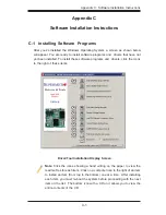
Page 97: ...ch item you must re boot the system before proceeding with the next item on the list The bottom icon with a CD on it allows you to view the entire contents of the CD Appendix C Software Installation Instructions C 1 Installing Software Programs After you ve installed the Windows Operating System a screen as shown below will appear You are ready to install software programs and drivers that have no...

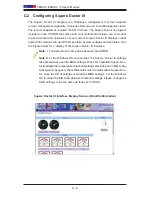
Page 98: ...III displays crucial system information such as CPU temperature system voltages and fan status See the Figure below for a display of the Supero Doctor III interface Note 1 The default user name and password are ADMIN Note 2 In the Windows OS environment the Supero Doctor III settings take precedence over the BIOS settings When first installed Supero Doc tor III adopts the temperature threshold set...

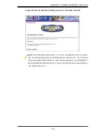
Page 99: ...ote Control Note SD III Software Revision 1 0 can be downloaded from our Web site at ftp ftp supermicro com utility Supero_Doctor_III You can also download SDIII User s Guide at http www supermicro com PRODUCT Manuals SDIII UserGuide pdf For Linux we will still recommend that you use Supero Doctor II ...

Page 100: ...C 4 X8DAH X8DAH F User s Manual Notes ...

Page 101: ... expected to result in significant injury or loss of life or catastrophic property damage Accordingly Supermicro disclaims any and all liability and should buyer use or sell such products for use in such ultra hazardous applications it does so entirely at its own risk Furthermore buyer agrees to fully indemnify defend and hold Supermicro harmless for and against any and all claims demands actions ...

Reviews: