


Chapter 2: Installation
2-31
JBT1
1
DP5 A
JPI2C1
CNF1
USB6/7
JLPC80
VGA
AUDIO
JPI1
JPG1
JWD1
JPT1
JPW2
JPW3
JPW1
SP1
FA
N
2
FA
N
6
FA
N
5
J14
JBAT1
JOH1
JL1
JI2C2
1
JI2C1
JD1
KB/MS
CD1
JIDE1
JWF1
USB
2/3/4/5
JUSB2
SMBUS1
ALWAYS POPULATE SLOT0 FIRST
Slot7 PCI-E 2.0 x8
FAN3
FA
N
1
P2 DIMM1C
P2 DIMM2C
P2 DIMM2B
P2 DIMM3B
P2 DIMM1B
P2 DIMM3C
P2 DIMM2A
P2 DIMM3A
P2 DIMM1A
P1 DIMM3C
P1 DIMM2C
P1 DIMM3B
P1 DIMM2B
P1 DIMM3A
P1 DIMM2A
P1 DIMM1C
P1 DIMM1B
P1 DIMM1A
ALWAYS POPULATE DIMM1 FIRST
CPU2 F
A
N
FLOPPY
IDE
I-SATA5
I-SATA4
I-SATA3
I-SATA2
I-SATA1
Slot6 PCI-E 2.0 x16
Slot5 PCI-E 2.0 x4 (in x8 Slot)
Slot4 PCI-E 2.0 x8 (in x16 Slot)
Slot3 PCI-E 2.0 x8
Slot2 PCI-E 2.0 x16
LAN2
COM1
I-SATA0
PWR I2C
CPU1
CPU2
USB0/1
LAN1
COM2
Slot1 PCI-E 2.0 x8
DP4
CNF2
BIOS
FA
N
4
FPCTL
JF1
FA
N
7
FA
N
1
CPU
LAN
CTRL
BMC
Audio
CTRL
BMC
Firmware
CTRL
5520
Intel
(NorthBridge)
5520
Intel
(NorthBridge)
ICH 10R
Intel
(SouthBridge)
X8DAH+
AUDIO
Header
7.1HD
BMC Graphics
Memory
S I/O
1394
CTRL
1394-1 1394-2
IPMI LAN
PHY
Chip
JPL1
JUSB1
J15
J139
JP4
JP5
JUSB5
JUSB4
Rev. 1.01
A
B
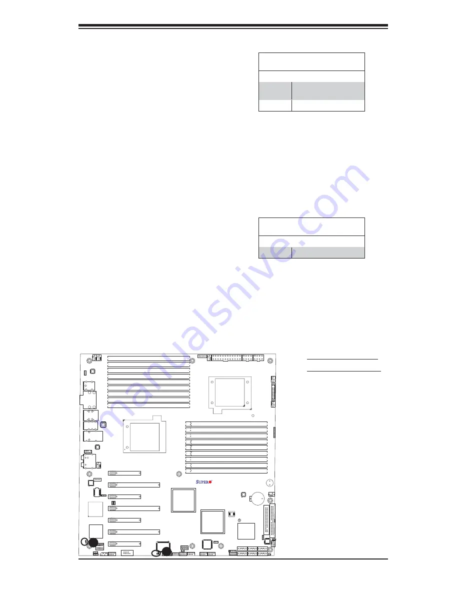
A. Onboard PWR LED
B. BMC Heartbeat LED
BMC Heartbeat LED (X8DAH+-F)
A BMC Heartbeat LED is located at DP5
on the motherboard. When DP5 is blink-
ing, BMC functions normally. See the
tables at right for more information.
Onboard Power LED
An Onboard Power LED is located at DP4
on the motherboard. When this LED is lit,
the system is on. Be sure to turn off the
system and unplug the power cord before
removing or installing components. See
the tables at right for more information.
Onboard PWR LED (DP4)
Settings
LED Color Defi nition
Off
System Off (PWR cable
not connected)
On
System Power On
BMC Heartbeat LED Indicator
(DP5) Settings
LED Color Defi nition
Blinking
BMC: Normal


