


2-22
SUPER P6DLS/P6DLE/P6SLS/P6SLA User’s Manual
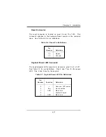
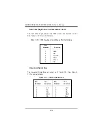
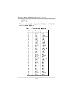
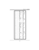
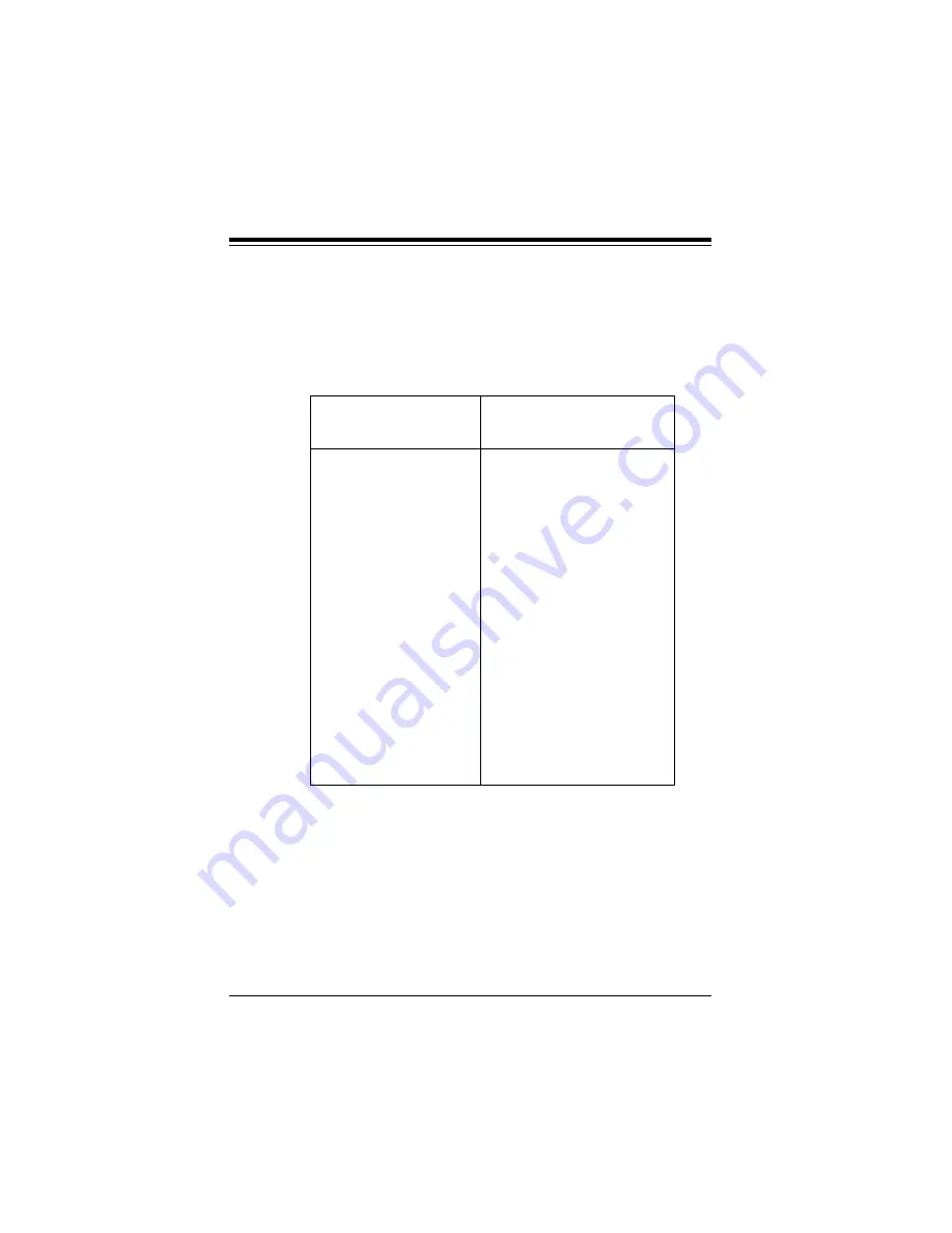
Floppy Connector
The floppy connector is located on J22. See Table 2-21 for pin
definitions.
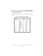
Table 2-21. Floppy Connector Pin Definitions
Pin
Pin
Number Function
Number Function
1
GND
2
FDHDIN
3
GND
4
Reserved
5
Key
6
FDEDIN
7
GND
8
Index-
9
GND
10
Motor Enable
11
GND
12
Drive Select B-
13
GND
14
Drive Select A-
15
GND
16
Motor Enable
17
GND
18
DIR-
19
GND
20
STEP-
21
GND
22
Write Data-
23
GND
24
Write Gate-
25
GND
26
Track 00-
27
GND
28
Write Protect-
29
GND
30
Read Data-
31
GND
32
Side 1 Select-
33
GND
34
Diskette
Summary of Contents for SUPER P6DLE
Page 1: ... SUPER SUPER P6DLS SUPER P6DLE SUPER P6SLS SUPER P6SLA USER S MANUAL Revision 1 2 ...
Page 11: ...1 3 Chapter 1 Introduction SUPER P6DLE Figure 1 2 SUPER P6DLE Motherboard Picture ...
Page 60: ...2 28 SUPER P6DLS P6DLE P6SLS P6SLA User s Manual ...
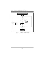
Page 65: ...3 5 Chapter 3 Troubleshooting ...
Page 66: ...3 6 SUPER P6DLS P6DLE P6SLS P6SLA User s Manual ...


