2-24
SUPER P6DLS/P6DLE/P6SLS/P6SLA User’s Manual
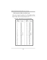
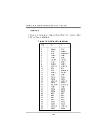
SCSI Connectors (P6DLS and P6SLS only)
There are no jumpers to configure the on-board SCSI interfaces
JA1 and JA2. Refer to Table 2-23 for the pin definitions for JA2.
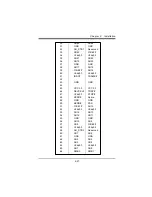
Refer to Table 2-24 for the pin definitions for JA1.
Table 2-23. 50-pin SCSI Connector Pin Definitions
Pin
Pin
Number Function
Number Function
1
GND
26
-DB (0)
2
GND
27
-DB (1)
3
GND
28
-DB (2)
4
GND
29
-DB (3)
5
GND
30
-DB (4)
6
GND
31
-DB (5)
7
GND
32
-DB (6)
8
GND
33
-DB (7)
9
GND
34
-DB (P)
10
GND
35
GND
11
GND
36
GND
12
Reserved
37
Reserved
13
Open
38
Termpwr
14
Reserved
39
Reserved
15
GND
40
GND
16
GND
41
-ATN
17
GND
42
GND
18
GND
43
-BSY
19
GND
44
-ACK
20
GND
45
-RST
21
GND
46
-MSG
22
GND
47
-SEL
23
GND
48
-C/D
24
GND
49
-REQ
25
GND
50
-I/O
Summary of Contents for SUPER P6DLE
Page 1: ... SUPER SUPER P6DLS SUPER P6DLE SUPER P6SLS SUPER P6SLA USER S MANUAL Revision 1 2 ...
Page 11: ...1 3 Chapter 1 Introduction SUPER P6DLE Figure 1 2 SUPER P6DLE Motherboard Picture ...
Page 60: ...2 28 SUPER P6DLS P6DLE P6SLS P6SLA User s Manual ...
Page 65: ...3 5 Chapter 3 Troubleshooting ...
Page 66: ...3 6 SUPER P6DLS P6DLE P6SLS P6SLA User s Manual ...

