


D-5
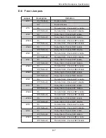
SCA-825S2 Backplane Specifications
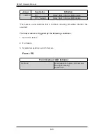
D-6 CD-ROM/Floppy Drive Power Connectors
The 4-pin power connectors supply power to the CD-ROM and floppy drives. See
the table below for pin definitions.
CD-ROM/Floppy Drive Four-Pin Power Connectors
Pin 1
+5V
Pins 2 and 3
Ground
Pin 4
+12V
D-5 GEM 318 Chip (SAF-TE: SCSI Accessed Fault-
Tolerant Enclosures)
This chip allows the system to use a set of pre-defined SCSI commands to moni
-
tor the status of disk drives and provide disk drive information to the user through
LED indicators and buzzers. (*Note: This function is available only when a RAID
controller with a RAID set is present and enabled. Please refer to the table below
for the information on SAF-TE LED indicators
.)
SAF-TE LED Indicators
SAF-TE LED Indicators
LED
Location
Description
D4
Front
Overheat or drive failure red light flashing, buzzer on
D5
Rear
Channel A ID#0 Failure LED red light flashing, buzzer on
DA5
Rear
Channel B ID#0 Failure LED red light flashing, buzzer on
D6
Rear
Channel A ID#1 Failure LED red light flashing, buzzer on
DA6
Rear
Channel B ID#1 Failure LED red light flashing, buzzer on
D16
Rear
Channel A ID#2 Failure LED red light flashing, buzzer on
DA16 Rear
Channel B ID#2 Failure LED red light flashing, buzzer on
D18
Rear
Channel A ID#3 Failure LED red light flashing, buzzer on
DA18 Rear
Channel B ID#3 Failure LED red light flashing, buzzer on


