


SC502 Chassis Manual
4-10
A
1
B
C
D
E
F
G
H
I
J
K
L
M
2
3
4
5
6
7
8
9
10
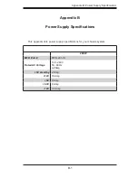
DESIGN / ³]-p :
MODEL NO./ ¾÷«¬ :
SIZE/¹Ï®Ø
APPROVED / ¼f®Ö :
DRAWN / ø¹Ï :
MATERIAL / §÷½è :
UNIT / ³æ¦ì :
FINISH / ªí-±³B¸Ì :
DATE / ¤é´Á:
DATE / ¤é´Á:
DATE / ¤é´Á:
TITLE / «~¦W :
PART NO. / ®Æ¸¹ :
Ablecom Technology Inc.
A
BLEC
DWG NO. / ¹Ï¸¹ :
¤j˚T¬ì§ÞªÑ¥÷¦³--¤½¥q
THE 3RD PROJECTION
²Ä¤T¨¤ªk
M
R E V I S I O N S / -×-q
REV
ª©¥»
DESCRIPTION
±Ô-z
LOCATION
¦ì¸m
DRAWN
-קïªÌ
DATE
¤é´Á
SC502_SYSTEM_ASSY
A0
*
SCALE / ¤ñ¨Ò :
1:1
SHEET
1
OF
1
SC502
*
SHO
29-Nov-07
See Note.
SHO
29-Nov-07
MM
*
REV.
ª©¥»
1
RANGE
½d³ò
TOLERANCE
¤½®t
X.xx
± 0.10
X.x
± 0.25
X
± 1.00
The SC502 chassis has a 200 watt power supply. This power supply is auto-switch-
ing capable. This enables it to automatically sense and operate at a 100v to 240v
input voltage.
The SC502 chassis has one power supply. In the unlikely event that the power
supply unit fails, the system will shut down and you will need to change the power
supply unit.
New units can be ordered directly from Supermicro (see contact information in the
Preface).
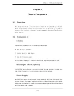
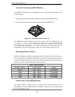
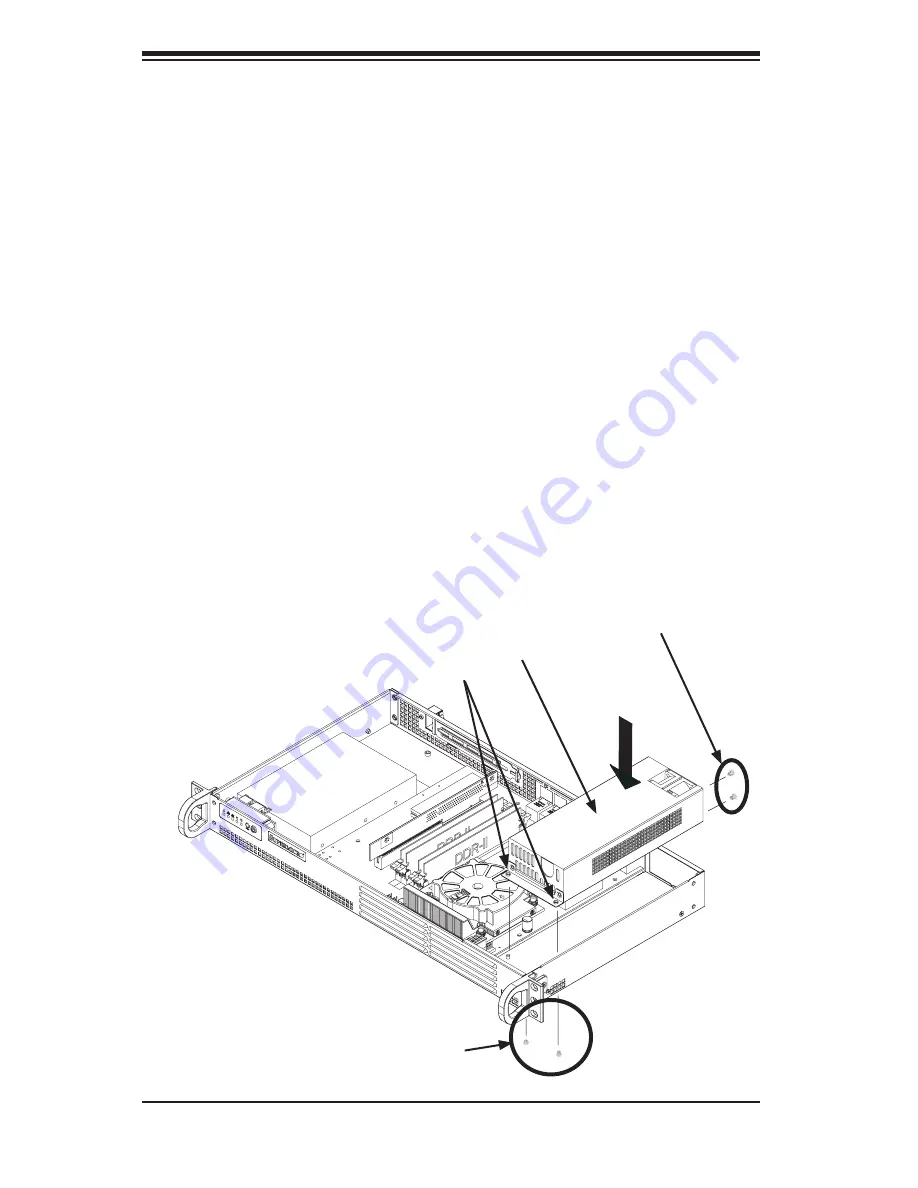
Replacing the Power Supply
Unplug all power leading to the chassis.
Disconnect all wiring from the power supply.
Remove the four screws which hold the power supply in the chassis. Two rear
mounting screws are located on the rear of the power supply. Two bottom
mounting screws are accessed on the underside of the chassis and extend
1.
2.
3.
4-8 Power Supply
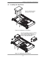
Figure 4-11: Installing the Power Supply
Power Supply
Mounting Thru Holes
Rear Mounting Screws
Bottom Mounting Screws
Summary of Contents for SC502 Series
Page 10: ...SC502 Chassis Manual 1 4 Notes ...
Page 28: ...SC502 Chassis Manual 4 12 Notes ...
Page 34: ...SC502 Chassis Manual 5 6 Notes ...