


3-1
Chapter 3: System Interface
Chapter 3
System Interface
3-1 Overview
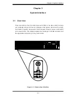
There are LEDs on the left control panel and LEDs on the drive carriers to keep
you constantly informed of the over-all status of the system, as well as the activity
and health of specific components. SC219 models include a power on/off button
and a reset button. This chapter explains the meanings of all LED indicators and
the appropriate responses you may need to take.
Figure 3-1: Chassis User Interface
SUPERMICR
®
Summary of Contents for SC219 Chassis Series
Page 8: ...SC219 Chassis Manual viii Notes ...
Page 12: ...SC219 Chassis Manual 1 4 Notes ...
Page 40: ...SC219 Chassis Manual 4 20 Notes ...
Page 50: ...SC219 Chassis Manual 5 10 Notes ...
Page 54: ...SC219 Chassis Manual A 4 Notes ...
Page 56: ...SC219 Chassis Manual B 2 Notes ...
Page 67: ...C 11 Appendix C SAS 213A Backplane Specifications Notes ...