Chapter 2: Installation
2-33
MAC CODE
IPMI CODE
BAR CODE
X10SRA-F
SW_BIOSRC
S4
S8
S11
CLR_CMOS_SW
JUSB30_I2
JA
UDIO1
I-SATA0
I-SATA2
I-SATA4
S-SATA0
S-SATA2
AUDIO_FP
JIPMB1
JSD1
MH11
MH2
MH9
MH10
JPW2
C
A
LEDM1
JBT1
BT1
+
FAN5
FAN4
FAN1
1
FAN2
4
FAN3
JPL2
JPUSB1
J29
J30
JP
ME2
JPAC1
JPL1
JI2C1 JI2C2
JPB1
JPG1
JWD1
1
JL2
JL1
JD1
1
JF1
2
19
JPI2C1
JSTBY1
JTP
M1
SP1
+
HD AUDIO
VGA
LAN1
LAN2
USB 16/17(3.0)
USB 12/13(3.0)
USB 10/11(3.0)
USB 14/15(3.0)
CPU SL
O
T6 PCI-E 3.0 X16
PCH SL
O
T5 PCI-E 2.0 X1 (IN X4)
CPU SL
O
T4 PCI-E 3.0 X8 (IN X16)
PCH SL
O
T3 PCI-E 2.0 X1 (IN X4)
CPU SL
O
T2 PCI-E 3.0 X8 (IN X16)
CPU SL
O
T1 PCI-E 3.0 X8 (IN X16)
2-3:DISABLE 1-2:ENABLE
:W
AT
CH DOG
SPEAKER PWR LED
:TP
M/POR
T80
CPU
CHASSIS INTRUSION
JI2C2
2-3:DISABLE 1-2:ENABLE JI2C1
PWR ON
OH/FF
NIC1
NIC2
RST
X
CMOS CLEAR
1-2:NORMAL
2-3:BIOS RECOVERY
JBR1
PWR LED
HDD LED
NMI
X
2-3:ME M
ANUF
AC
TURING MODE
JP
ME2
1-2:NORM
AL
1-2 ENABLE
2-3 DISABLE
1-2 ENABLE
2-3 DISABLE
:PWR I2C
1-2 ENABLE
2-3 DISABLE
2-3 DISABLE 1-2 ENABLE
1-2 ENABLE
2-3 DISABLE
JPAC1
VGA
USB14/15 WAKE UP
1-2 RST
2-3 NMI
:SATA DOM POWER
DIMMD2
DIMMD1
DIMMC2
DIMMC1
DIMMB2
DIMMB1
DIMMA2
DIMMA1
JBR1
JWD1
JPW1
JPUSB1
JPB1
JPG1
C
A
LE2
I-SATA1
I-SATA3
I-SATA5
S-SATA1
S-SATA3
X10SRA/
COM1
LED4
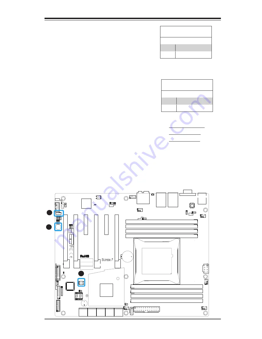
BIOS Recovery Switch (JBR1)
The BIOS Recovery Switch (JBR1) is used
to enable or disable the BIOS Recovery
feature of the motherboard. Slide the
switch from the default position to begin
the recovery process. See Appendix D
for details.
Power Button (S4)
In addition to the soft power switch
provided in JF1, your motherboard is
equipped with a 'soft' power button on
the motherboard. This switch works the
same way as the soft power switch on
JF1.
BIOS Recovery (JBR1)
Jumper Settings
State Definition
Off
Normal (Default)
On
Recover
Manufacture Mode (JPME2)
Jumper Settings
Pin# Definition
1-2
Normal (Default)
2-3
Manufacture Mode
A. BIOS Recovery
B. Power Button
C. BIOS Restore
A
B
BIOS Restore (S11)
When pressed, the BIOS Restore Button
will look for, and load a file named 'SU
-
PER.ROM' from an installed USB memory
device, in any of the USB ports. It will
then proceed to update the BIOS. Do
NOT turn off the system when BIOS is
updating.
C
Summary of Contents for MBD-X10SRA-F-O
Page 1: ...X10SRA X10SRA F USER S MANUAL Revision 1 1b...
Page 18: ...xviii Supermicro X10SRA X10SRA F Motherboard User s Manual Notes...
Page 30: ...1 12 Supermicro X10SRA X10SRA F Motherboard User s Manual Notes...
Page 124: ...A 2 Supermicro X10SRA X10SRA F Motherboard User s Manual Notes...
Page 128: ...B 4 Supermicro X10SRA X10SRA F Motherboard User s Manual Notes...


