


6-2
AS2021M-32R User's Manual
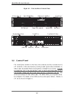
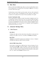
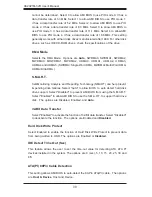
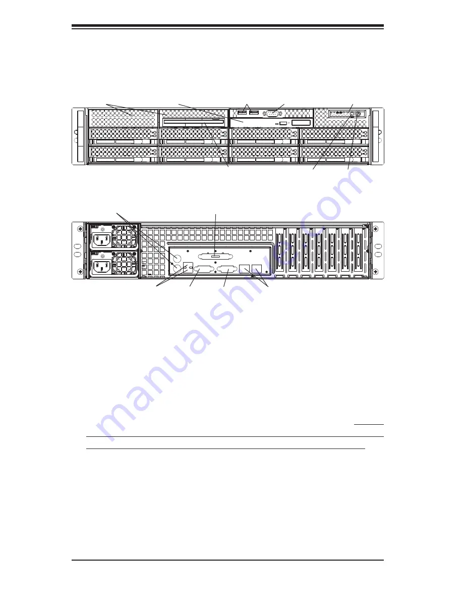
Figure 6-1. Front and Rear Chassis Views
System Reset
6-2 Control
Panel
The control panel (located on the front of the chassis) must be connected to the
JF1 connector on the serverboard to provide you with system status indications. A
ribbon cable has bundled these wires together to simplify the connection. Connect
the cable from JF1 on the serverboard to JP4 on the Control Panel PCB (printed
circuit board). Make sure the red wire plugs into pin 1 on both JF1 and JP4. Pull
all excess cabling out of the airfl ow path. The LEDs inform you of system status.
See Chapter 3 for details on the LEDs and the control panel buttons. Details on
JF1 can be found in Chapter 5.
Control Panel
Main Power
Slim DVD-ROM Drive
3.5" Drive Bays (2)
SAS Drives (8)
Floppy Drive (optional)
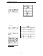
Ethernet Ports
USB Ports
Keyboard/Mouse Ports
COM1 Port
7 Low-Profi le PCI Slots
VGA Port
USB Ports (2), COM Port
Parallel Port
Summary of Contents for AS-2021M-32R
Page 1: ...AS2021M 32R USER S MANUAL 1 0a SUPER ...
Page 5: ...v Preface Notes ...
Page 10: ...Notes x AS2021M 32R User s Manual ...
Page 16: ...1 6 AS2021M 32R User s Manual Notes ...
Page 21: ...Chapter 2 Server Installation 2 5 Figure 2 1 Installing Chassis Rails ...
Page 23: ...Chapter 2 Server Installation 2 7 Figure 2 2 Installing the Server into a Rack ...
Page 25: ...Chapter 2 Server Installation 2 9 Figure 2 3 Accessing the Inside of the System ...
Page 30: ...AS2021M 32R User s Manual 3 4 Notes ...
Page 62: ...5 28 AS2021M 32R User s Manual Notes ...
Page 88: ...7 18 AS2021M 32R User s Manual Notes ...
Page 90: ...A 2 AS2021M 32R User s Manual Notes ...


