Chapter 6: Advanced Chassis Setup
6-3
6-3 Control Panel
The front control panel LEDs help monitor the system status. See Chapter 3 for
details on the LEDs and buttons.
The control panel connects to the JF1 connector on the serverboard to provide
system status indications. The red wire in the ribbon cable plugs into pin 1 on both
connectors. Details on JF1 can be found in Chapter 5. Pull all excess cable out of
the airflow path.
Control Panel Orientation
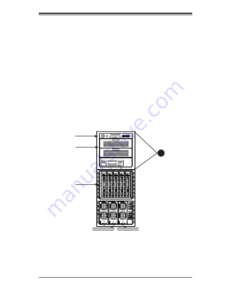
The server can be configured for either tower or server rack orientation. It is shipped
in tower mode and can be immediately used as desktop server. To use it in a rack,
rotate the module that contains the control panel and the three drive trays (#1 in
Figure 6-2) 90 degrees.
Figure 6-2. Chassis in Tower Mode
(Default Configuration)
Storage Module
Drive Trays
Control Panel
1
Control Panel/
Drive Module
Summary of Contents for 4042G-72RF4
Page 1: ... SUPER A SERVER 4042G 72RF4 USER S MANUAL Revision 1 0b ...
Page 23: ...Chapter 2 Server Installation 2 9 Figure 2 5 Accessing the Inside of the System ...
Page 80: ...5 32 A SERVER 4042G 72RF4 USER S MANUAL Notes ...
Page 98: ...6 18 A SERVER 4042G 72RF4 USER S MANUAL Notes ...
Page 118: ...A 2 A SERVER 4042G 72RF4 USER S MANUAL Notes ...


