Supermicro SUPERSERVER 6028R-TDWNR User Manual Download Page 45

Chapter 6: Advanced Chassis Setup

6-3

6-2

S

UPER

S

ERVER 6028R-TDWNR User's Manual

6-4  System Fans

Three 8-cm hot-swap fans provide the cooling for the system. It is very important 
that the chassis top cover is properly installed and making a good seal in order for 
the cooling air to circulate properly through the chassis and cool the components.

System Fan Failure

Fan speed is controlled by system temperature via IPMI. If a fan fails, the remaining 
fans will ramp up to full speed and the overheat/fan fail LED on the control panel will 
turn on. Replace any failed fan at your earliest convenience with the same type and 
model (the system can continue to run with a failed fan). Remove the top chassis 
cover while the system is still running to determine which of the fans has failed.

Figure 6-1.  Front and Rear Chassis Views

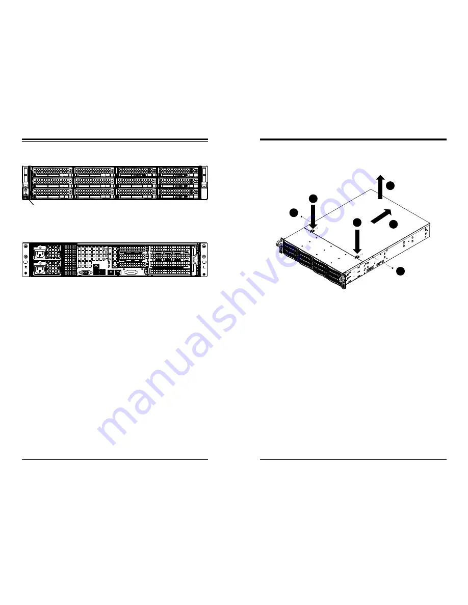
Figure 6-2.  Removing the Chassis Cover

6-2  Control Panel

The control panel (located on the front of the chassis) must be connected to the 
JF1 connector on the serverboard to provide you with system status indications. A 
ribbon cable has bundled these wires together to simplify the connection. Connect 
the cable from JF1 on the serverboard to the Control Panel PCB (printed circuit 
board). Make sure the red wire plugs into pin 1 on both connectors. Pull all excess 

cabling out of the airflow path. The LEDs inform you of system status.

See Chapter 3 for details on the LEDs and the control panel buttons. Details on 
JF1 can be found in Chapter 5.

6-3  Accessing the Inside of the Chassis

Some maintenance will require accessing the inside of the server. 

Removing the Chassis Cover (Figure 6-2)

1.  Remove the two screws from the sides of the chassis cover.

2.  Press both release tabs at the same time to unlock the cover.

3.  Slide the cover toward the rear of the chassis.

4.  Lift the cover off the chassis.

1

1

1

1

1

3

1

2

1

2

1

4

Caution: 

Except for short periods of time, do not operate the server without the chas-

sis  cover  in  place.  The  cover  must  be  in  place  to  allow  proper  airflow  and  prevent 

overheating.

Power Supplies

PCI Expansion Slots

I/O Ports

Note:

 NVMe drive bays are outlined above (four total).

Control Panel

SATA/NVMe Hard Drives (12)

Summary of Contents for SUPERSERVER 6028R-TDWNR

Page 1: ...SUPERSERVER 6028R TDWNR USER S MANUAL 1 0a...

Page 2: ...said license IN NO EVENT WILL SUPERMICRO BE LIABLE FOR DIRECT INDIRECT SPECIAL INCIDENTAL SPECULATIVE OR CONSEQUENTIAL DAMAGES ARISING FROM THE USE OR INABILITY TO USE THIS PRODUCT OR DOCUMENTATION E...

Page 3: ...ring the serverboard Chapter 6 Advanced Chassis Setup Refer to Chapter 6 for detailed information on the SC826BAC4 R920WB server chassis You should follow the procedures given in this chapter when ins...

Page 4: ...VER 6028R TDWNR User s Manual NIC1 3 2 NIC2 3 3 HDD 3 3 Power 3 3 3 4 Drive Carrier LEDs 3 3 3 5 Power Supply LEDs 3 4 Chapter 4 Standardized Warning Statements for AC Systems 4 1 About Standardized W...

Page 5: ...6 3 Accessing the Inside of the Chassis 6 2 6 4 System Fans 6 3 System Fan Failure 6 3 Replacing System Fans 6 4 6 5 Air Shroud 6 5 6 6 Drive Bay Installation Removal 6 6 Accessing the Drive Bays 6 6...

Page 6: ...P 310 29017 0B Two passive CPU heatsinks SNK P0048PS Two riser cards RSC R2UW 2E8E16 and RSC R2UW E8R UP SATA Accessories One hard drive backplane BPN SAS3 826A N4 Eight drive SATA carriers MCP 220 00...

Page 7: ...U The NVMe drives are hot swappable PCI Expansion Two riser cards have been pre installed in the system to support PCI expansion cards The RSC R2UW 2E8E16 can support two full height half length PCI E...

Page 8: ...Jian 1st Rd Zhonghe Dist New Taipei City 235 Taiwan R O C Tel 886 2 8226 3990 Fax 886 2 8226 3992 Email support supermicro com tw Website www supermicro com tw x16 P1 P1 P0 P0 CPU FRONT CPU DMI PE1 P...

Page 9: ...1 6 SUPERSERVER 6028R TDWNR User s Manual Notes...

Page 10: ...suitable location for the rack unit that will hold the 6028R TDWNR It should be situated in a clean dust free area that is well ventilated Avoid areas where heat electrical noise and electromagnetic...

Page 11: ...f installed in a closed or multi unit rack assembly the ambient operating tempera ture of the rack environment may be greater than the ambient temperature of the room Therefore consideration should be...

Page 12: ...to mount the chassis in the rack Installing the Inner Rails 1 Place the inner rail extensions on the side of the chassis aligning the hooks of the chassis with the rail extension holes Make sure the...

Page 13: ...he bottom of the rack first Figure 2 2 Assembling the Outer Rails screw the handles the outer rails for secure purpose if necessary F ABLECOM DATE 2008 08 14 REV 2 SCREW SCREW COMPLETE 1 2 1 1 1 2 1 3...

Page 14: ...2 8 SUPERSERVER 6028R TDWNR User s Manual Notes...

Page 15: ...of specific components There are also two buttons on the chassis control panel 3 2 Control Panel Buttons There are two buttons located on the front of the chassis a reset button and a power on off bu...

Page 16: ...Indicates a power supply module has failed The second power supply module will take the load and keep the system running but the failed module will need to be replaced Refer to Chapter 6 for details o...

Page 17: ...the CPU and the NVMe SSD drives 3 5 Power Supply LEDs On the rear of the power supply module an LED displays the status Solid Green When illuminated indicates that the power supply is on Solid Amber...

Page 18: ...nt for assistance Only certified technicians should attempt to install or configure components Read this appendix in its entirety before installing or configuring components in the Supermicro chassis...

Page 19: ...partado de traducciones que acompa a a este dispositivo GUARDE ESTAS INSTRUCCIONES IMPORTANTES INFORMATIONS DE S CURIT Ce symbole d avertissement indique un danger Vous vous trouvez dans une situation...

Page 20: ...re that the protective device is rated not greater than 250 V 20 A Waarschuwing Raadpleeg de installatie instructies voordat u het systeem op de voedingsbron aansluit 250 V 20 A Warnung Dieses Produkt...

Page 21: ...veiliging overspanning van uw electrische installatie Controleer of het beveiligde aparaat niet groter gedimensioneerd is dan 220V 20A Advertencia El sistema debe ser disconnected de todas las fuentes...

Page 22: ...confier l installation le remplacement et la maintenance de ces quipements des personnels qualifi s et exp riment s Waarschuwing Deze apparatuur mag alleen worden ge nstalleerd vervangen of hersteld...

Page 23: ...e semblable ou quivalent recommand e par le fabricant Jeter les piles usag es conform ment aux instructions du fabricant Advertencia Existe peligro de explosi n si la bater a se reemplaza de manera in...

Page 24: ...e Warnung Wenn das System in Betrieb ist treten auf der R ckwandplatine gef hrliche Spannungen oder Energien auf Vorsicht bei der Wartung Advertencia Cuando el sistema est en funcionamiento el voltaje...

Page 25: ...roduct Disposal Warning Ultimate disposal of this product should be handled according to all national laws and regulations Backplane Waarschuwing Een gevaarlijke spanning of energie is aanwezig op de...

Page 26: ...housing Hot Swap Fan Warning Warnung Die L fter drehen sich u U noch wenn die L fterbaugruppe aus dem Chassis genommen wird Halten Sie Finger Schraubendreher und andere Gegenst nde von den ffnungen de...

Page 27: ...ehlfunktion oder ein Brand entstehen Elektrische Ger te und Material Safety Law verbietet die Verwendung von UL oder CSA zertifizierte Kabel UL oder CSA auf der Code f r alle anderen elektrischen Ger...

Page 28: ...4 20 SUPERSERVER 6028R TDWNR User s Manual Notes...

Page 29: ...that the size and weight of the serverboard can cause it to bend if handled improperly which may result in damage To prevent the serverboard from bending keep one hand under the center of the board to...

Page 30: ...e LGA 2011 socket First press and release the load lever labeled Open 1st OPEN1st OPEN1st Release the lever labeled Close 1st 2 Press the second load lever labeled Close 1st to release the load plate...

Page 31: ...ly the proper amount of thermal grease before you re install the heatsink Screw 1 Screw 3 Screw 2 Screw 4 Installing a CPU Heatsink 1 Place the heatsink on top of the CPU so that the four mounting hol...

Page 32: ...ower connector pin definitions In addition your power supply must be connected to the 8 pin Processor Power connectors at JPWR1 and JPWR2 Connecting the Control Panel JF1 contains header pins for vari...

Page 33: ...P1 DIMMD1 P1 DIMMA2 P1 DIMMB2 P1 DIMMC2 P1 DIMMD2 CPU2 P2 DIMME1 P2 DIMMF1 P2 DIMMG1 P2 DIMMH1 P2 DIMME2 P2 DIMM F2 P2 DIMMG2 P2 DIMMH2 Processor and Memory Module Population for Optimal Performance N...

Page 34: ...the chassis align the mezzanine card with slot JMEZ1 MOTHERBOARD MEZZANINE CARD 2 Using both hands press the mezzanine card down into the slot BAR CODE JD1 SP1 JIPMB1 JPI2C1 I SGPIO2 J23 BT1 JI2C2 JI2...

Page 35: ...sabled JPB1 BMC Enable Disable Pins 1 2 Enabled JPG1 VGA Enable Disable Pins 1 2 Enabled JPLAN1 GLAN1 GLAN2 Enable Disable Pins 1 2 Enabled JPME2 Manufacture ME Mode Select Pins 1 2 Normal JWD1 Watch...

Page 36: ...D Processor Power Connectors JPWR1 and JPWR2 must also be connected to the power supply to provide power for the processor s See the table on the right for pin definitions ATX Power 24 pin Connector P...

Page 37: ...e computer case Refer to the table on the right for pin definitions Reset Button Pin Definitions JF1 Pin Definition 3 Reset 4 Ground Power Button The Power Button connection is located on pins 1 and 2...

Page 38: ...ports to provide a dedicated network connection for IPMI 2 0 These ports accept RJ45 type cables Please refer to Section 5 11 for LAN LED information Power SMB I2 C Connector The Power System Managem...

Page 39: ...de posted on our website at http www supermicro com UID Switch Pin Definition 1 Ground 2 Ground 3 Button In 4 Button In UID LED Status Color State Status Blue On Unit Identified 5 10 Jumper Settings E...

Page 40: ...oller to provide IPMI 2 0 KVM support on the serverboard See the table on the right for jumper settings BMC Enable Disable Jumper Settings Jumper Setting Definition Pins 1 2 BMC Enabled Pins 2 3 Norma...

Page 41: ...g normally See the table on the right for more information BMC Heartbeat LED States Color State Definition Green Blinking BMC Normal 5 12 SATA Ports SATA Ports Ten SATA ports are provided on the serve...

Page 42: ...l each item from top to the bottom one at a time After installing each item you must re boot the system before moving on to the next item on the list The bottom icon with a CD on it allows you to view...

Page 43: ...f this practice is not strictly followed Figure 5 7 Installing the Onboard Battery OR Please handle used batteries carefully Do not damage the battery in any way a damaged battery may release hazardou...

Page 44: ...em very carefully The following measures are generally sufficient to protect your equipment from ESD damage Precautions Use a grounded wrist strap designed to prevent static discharge Touch a grounded...

Page 45: ...the serverboard to provide you with system status indications A ribbon cable has bundled these wires together to simplify the connection Connect the cable from JF1 on the serverboard to the Control P...

Page 46: ...er to replace or swap hard drives Up to eight SATA and four NVMe drives may be installed in the server Drive Installation The drives are mounted in carriers to simplify their installation and removal...

Page 47: ...Backplane 3 2 1 4 BAR CODE DESIGNED IN USA BPN SAS3 826A N4 REV 1 00 44 34 11 12 23 33 44 34 11 12 22 23 33 1 2 5 6 1 2 5 6 1 3 1 3 1 3 1 4 1 4 1 4 1 4 A1 A2 CG1 B1 B2 C1 C2 D1 D2 CG2 B7 B8 C8 A7 C7 D...

Page 48: ...Supermicro The power supply units have a hot swap capability meaning you can replace the failed unit without powering down the system Removing Replacing the Power Supply You do not need to shut down...

Page 49: ...6 10 SUPERSERVER 6028R TDWNR User s Manual Notes...

Page 50: ...tions cannot be configured Options in blue can be configured by the user The right frame displays the key legend Above the key legend is an area reserved for a text message When an option is selected...

Page 51: ...memory modules installed in the system How to Start the Setup Utility Normally the only visible Power On Self Test POST routine is the memory test As the memory is being tested press the Delete key to...

Page 52: ...r rupt 19 at bootup immediately and allow the drives that are attached to these host adaptors to function as bootable disks If this item is set to Postponed the ROM BIOS of the host adaptors will not...

Page 53: ...dresses to improve network connectivity and system performance The options are Enable and Disable X2APIC Advanced Programmable Interrupt Controller Based on Intel s Hyper Threading architecture each l...

Page 54: ...tate is also known as SpeedStep for Intel processors Select HW_ALL to change the P state coordination type for hardware components only Select SW_ALL to change the P state coordination type for all so...

Page 55: ...ptions are Gen1 Gen2 and Gen3 IIO2 Configuration IIO 2 IOU1 PCIe Port This item configures the PCI E port Bifuraction setting for a PCI E port specified by the user The options are x4x4 x8 and Auto Po...

Page 56: ...ct Enable for Link L1 support The options are Enable and Disable COD Enable Available when the OS and the CPU support this feature Select Enabled for Cluster On Die support to enhance system performan...

Page 57: ...u to decide how many hours the system should wait before the next complete patrol scrub is performed Use the keyboard to enter a value from 0 24 The Default setting is 24 Demand Scrub Demand Scrubbing...

Page 58: ...gure a SATA drive specified by the user as an IDE drive Select AHCI to configure a SATA drive specified by the user as an AHCI drive Select RAID to configure a SATA drive specified by the user as a RA...

Page 59: ...SATA port Model number of drive and capacity Software Preserve Support SATA Port 0 Port 5 Select Enabled to enable a SATA port specified by the user The options are Disabled and Enabled Port 0 Port 5...

Page 60: ...en the I O becomes active The options are Enabled and Disabled sSATA RAID Option ROM UEFI Driver Select EFI to load the EFI driver for system boot Select Legacy to load a legacy driver for system boot...

Page 61: ...size must be between 4032G to 4078G The options are 56T 48T 24T 2T 512G and 256G MMIO High Size Use this item to select the high memory size according to memory address mapping for the PCH The option...

Page 62: ...used in the host computer and the client computer A lower transmission speed may be required for long and busy lines The options are 9600 19200 38400 57600 and 115200 bits per second Data Bits Use thi...

Page 63: ...Data Bits Use this feature to set the data transmission size for Console Redirection The options are 7 Bits and 8 Bits Parity A parity bit can be sent along with regular data bits to detect data trans...

Page 64: ...into one or more bytes The options are ANSI VT100 VT100 and VT UTF8 Bits Per Second This item sets the transmission speed for a serial port used in Console Redirec tion Make sure that the same speed i...

Page 65: ...PCI devices The options are Disabled and Enabled iSCSI Configuration This item displays iSCSI configuration information iSCSI Initiator Name This item displays the name of the iSCSI Initiator which is...

Page 66: ...t before generating a new event log Enter a number between 0 to 99 The default setting is 60 Note Please reboot the system for the changes to take effect View SMBIOS Event Log This item allows the use...

Page 67: ...l server attached to the network and request the next available IP address for this computer The options are DHCP and Static Station IP Address This item displays the Station IP address for this compu...

Page 68: ...Boot Option 10 Boot Option 11 Boot Option 12 Boot Option 13 Boot Option 14 Boot Option 15 Add New Boot Option Use this item to select a new boot device to add to the boot priority list Add Boot Optio...

Page 69: ...t from the Exit menu and press Enter Save Changes and Reset When you have completed the system configuration changes select this option to leave the BIOS setup utility and reboot the computer for the...

Page 70: ...ve as User Defaults from the Exit menu and press En ter This enables the user to save any changes to the BIOS setup for future use Restore User Defaults To set this feature select Restore User Default...

Page 71: ...fatal errors are usually communicated through a series of audible beeps The numbers on the fatal error list correspond to the number of beeps for the cor responding error Motherboard BIOS Error Beep C...

Page 72: ...A 2 SUPERSERVER 6028R TDWNR User s Manual Notes...

Page 73: ...2 TB of DDR4 2400 2133 1866 1600 ECC LRDIMM Load Reduced DIMMs or 512 GB of ECC RDIMM registered DIMMs DDR4 2400 2133 1866 1600 memory See the memory section in Chapter 5 for details SATA Intel on chi...

Page 74: ...ng Temperature 40 to 70 C 40 to 158 F Operating Relative Humidity 8 to 90 non condensing Non operating Relative Humidity 5 to 95 non condensing Regulatory Compliance Electromagnetic Emissions FCC Clas...

Page 75: ...erform be reasonably expected to result in significant injury or loss of life or catastrophic property damage Accordingly Supermicro dis claims any and all liability and should buyer use or sell such...

Reviews: