


6-2
S
UPER
S
ERVER 5018D-MHR7N4P User's Manual
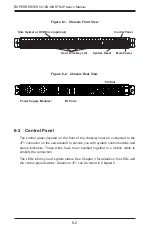
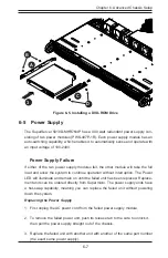
Figure 6-2. Chassis Rear View
6-2 Control Panel
The control panel (located on the front of the chassis) must be connected to the
JF1 connector on the serverboard to provide you with system control buttons and
status indicators. These wires have been bundled together in a ribbon cable to
simplify the connection.
The LEDs inform you of system status. See Chapter 3 for details on the LEDs and
the control panel buttons. Details on JF1 can be found in Chapter 5.
Figure 6-1. Chassis Front View
Power Supply Modules*
I/O Ports
PCI Slot
Hard Drive Bays (4)
Control Panel
System Reset
Slim Optical or DVD Drive (optional)
Main Power
Summary of Contents for SUPERSERVER 5018D-MHR7N4P
Page 1: ...SUPERSERVER 5018D MHR7N4P USER S MANUAL 1 0 ...
Page 5: ...Notes Preface v ...
Page 14: ...1 6 SUPERSERVER 5018D MHR7N4P User s Manual Notes ...
Page 116: ...7 40 SUPERSERVER 5018D MHR7N4P User s Manual Notes ...
Page 118: ...A 2 SUPERSERVER 5018D MHR7N4P User s Manual Notes ...