


3-1
Chapter 3: System Interface
Chapter 3
System Interface
3-1 Overview
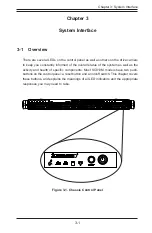
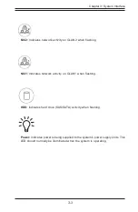
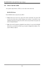
There are several LEDs on the control panel as well as others on the drive carriers
to keep you constantly informed of the overall status of the system as well as the
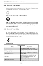
activity and health of specific components. Most SC813M models have two push-
buttons on the control panel: a reset button and an on/off switch. This chapter covers
these buttons, and explains the meanings of all LED indicators and the appropriate
responses you may need to take.
Figure 3-1. Chassis Control Panel
Summary of Contents for SUPERSERVER 5018D-MHR7N4P
Page 1: ...SUPERSERVER 5018D MHR7N4P USER S MANUAL 1 0 ...
Page 5: ...Notes Preface v ...
Page 14: ...1 6 SUPERSERVER 5018D MHR7N4P User s Manual Notes ...
Page 116: ...7 40 SUPERSERVER 5018D MHR7N4P User s Manual Notes ...
Page 118: ...A 2 SUPERSERVER 5018D MHR7N4P User s Manual Notes ...