
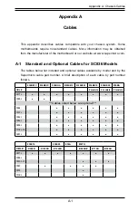


C-6
SC836 Chassis Manual
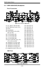
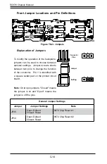
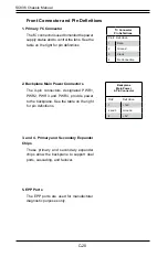
Front Jumper Locations and Pin Definitions
Explanation of Jumpers
To modify the operation of the backplane,
jumpers can be used to choose between
optional settings. Jumpers create shorts
between two pins to change the function
of the connector. Pin 1 is identified with
a square solder pad on the printed circuit
board.
Note: On two pin jumpers, "Closed" means
the jumper is on and "Open" means the
jumper is off the pins.
Connector
Pins
Jumper
Setting
3 2 1
3 2 1
General Jumper Settings
Jumper
Jumper Settings
Note
JP35
Open: Default
Closed: Reset
MG9072 chip reset #1
JP50
Open: Default
Closed: Reset
MG9072 chip reset #2
JP61
JP98
JP97
JP62
JP99
JP100
JP84
JP50
JP63
JP64
JP35
Figure A-2. Front Jumpers
Summary of Contents for SC836 Series
Page 8: ...SC836 Chassis Manual viii Notes ...
Page 12: ...SC836 Chassis Manual 1 4 Notes ...
Page 32: ...2 20 SC836 Chassis Manual Notes ...
Page 38: ...SC836 Chassis Manual 3 6 Notes ...


