


E-9
Appendix E: CB3 JBOD Control Board
JP1
JP3
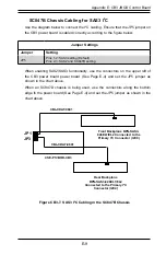
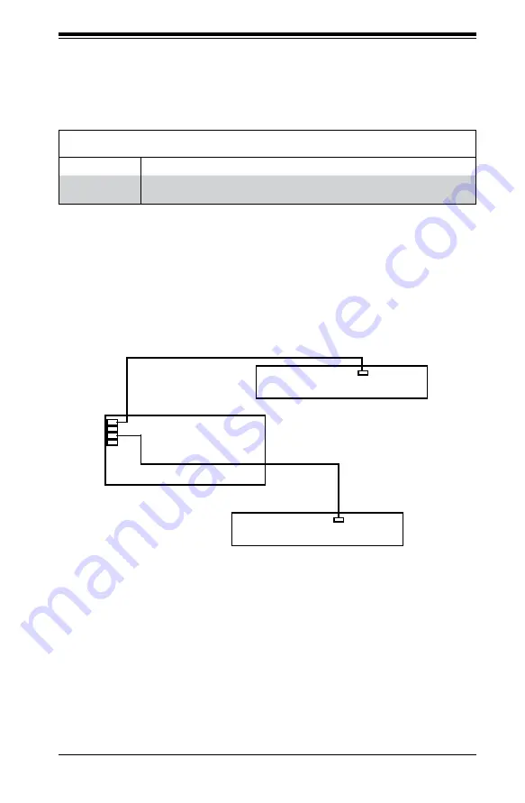
SC847B Chassis Cabling for SAS3 I
2
C
Use the diagram below to connect the I
2
C cabling. Ensure that the JP5 jumper on
the CB3 power board is cabled correctly according to the figure below.
CSE-PTJBOD-CB3
Figure CB3-7. SAS3 I
2
C Cabling in the SC847B Chassis
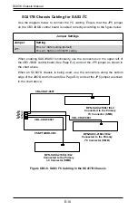
Jumper Settings
Jumper
Setting
JP5
Pins 1-2: SAS3 setting (Default)
Pins 2-3: SAS2 and SC847D setting
Rear Backplane
BPN-SAS3-826EL1/EL2
Connected to the Primary I
2
C
Connector (I2C4)
Front Backplane BPN-SAS3-
846EL1/EL2 Connected to the
Primary I
2
C Connector (I2C0)
CBL-CDAT-0601
CBL-CDAT-0601
When enabling SAS2/SAS3 functionality, use the connectors on the upper left of
the CB3 power board power board (See Page E-4) and set the JP5 jumper as
shown in the chart above.
When an SC847D chassis is being used, use the connectors along the bottom
edge fo the power board (See Page E-4) and set the JP5 jumper as shown in the
chart above.
Summary of Contents for SC836 Series
Page 8: ...SC836 Chassis Manual viii Notes ...
Page 12: ...SC836 Chassis Manual 1 4 Notes ...
Page 32: ...2 20 SC836 Chassis Manual Notes ...
Page 38: ...SC836 Chassis Manual 3 6 Notes ...