G-3
Appendix G: Connectors Jumpers and LEDs
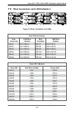
G-4 Rear Connector Locations
The following connectors are on the side of the backplane that faces the rear of the
chassis. They are marked by silkscreen labels.
A
1
E
5
H
5
1
A
E
H
A
C
A
C
1
7
25
26
50
51
75
76
100
1
3
1
3
BPN-SAS3-826EL1-N4
REV:1.00
SAS CODE
A
C
A
C
A
C
A
C
+
+
+
+
3
2
1
4
3
2
1
4
1
4
1
4
1
4
1
4
1
4
6
7
8
9
13
12
22
A1 A2
A7
A8
CG
1
CG
2
B1
B2
B7
B8
C1
C2
C7
C8
D1
D2
D7
D8
CG
3
E1
E2
G2
F2
F1
H2
H1
G1
F7
F8
G8
E7
G7
H7
H8
E8
PRESS FIT
A1
A2
A7
A8
CG
1
CG
2
B1
B2
B7
B8
C1
C2
C7
C8
D1
D2
D7
D8
CG
3
E1
E2
G2
F2
F1
H2
H1
G1
F7
F8
G8
E7
G7
H7
H8
E8
PRESS FIT
A1
A2
A7
A8
CG
1
CG
2
B1
B2
B7
B8
C1
C2
C7
C8
D1
D2
D7
D8
CG
3
E1
E2
G2
F2
F1
H2
H1
G1
F7
F8
G8
E7
G7
H7
H8
E8
PRESS FIT
A1 A2
A7
A8
CG
1
CG
2
B1
B2
B7
B8
C1
C2
C7
C8
D1
D2
D7
D8
CG
3
E1
E2
G2
F2
F1
H2
H1
G1
F7
F8
G8
E7
G7
H7
H8
E8
PRESS FIT
1
5
10
15
20
25
26
AF
AE
Y
R
K
E
A
1
2
3
1
2
3
1
DESIGNED IN USA
BAR CODE
67
12
13
24
7
12
24
U136
R399
Q43
L2
D32
D31
JP2
J24
J23
L3
Q17
L1
LED29
LED27
LED26
LED25
L29
C188
C19
4
C192
C193
J21
J20
U22
J22
J18
JPW2
JPW1
JPW3
U11
OSC1
U143
U19
U14
U13
U16
U3
C7
C6
C206
C205
C186
C187
J15
J14
J16
J17
MH7
MH6
MH9
MH8
MH5
MH1
MH2
MH3
U9
U30
U7
JP1
U26
R44
R400
R1
08
R97
R1
10
R183
R182
C30
C17
C486
C485
C14
CPU2
0
3
2
1
: 2
: 3
: 1
: 4
CPU1
J24
2-3
2-3
1-2
1-2
1-2
1-2
2-3
2-3
J23
NVM
e4
NVM
e3
NVMe2
NVM
e1
CPLD
SAS P1
SAS P3
SAS P2
SAS P4
I2C#4
UART
12V
5V
HB-LED
SDB
I2C#0
TEST
ACT-LED
1. Power Connectors, 4-pin: JPW1,
JPW2 and JPW3.
2. SAS Connector for SASP1-
SASP2: J14.
3. SAS Connector for SASP3-
SASP4: J15.
4. NVMe Connector for NVMe2 and
NVMe3: J16. Note: Top connects
to NVMe3, bottom connects to
NVMe2.
5. NVMe Connector for NVMe1 and
NVMe4: J17. Note: Top connects
to NVMe1 and bottom connects
to NVMe4.
6. SDB Connector: J18.
7. UART Connector: J22.
8. I
2
C Connector I2C#0: J20.
9. I
2
C Connector I2C#4: J21.
10. CPLD Upgrade Connector: JP2.
1
1
1
1
1
1
1
2
1
4
1
3
1
5
1
8
1
9
1
10
6
6
1
7
Figure 2-1. Rear Connectors
Summary of Contents for SC826 Series
Page 12: ...SC826 Chassis Manual 1 6 Notes ...
Page 56: ...SC826 Chassis Manual 4 18 Figure 4 16 Placing the System Fan in the Chassis 3 5 ...
Page 60: ...SC826 Chassis Manual 4 22 Notes ...
Page 72: ...SC826 Chassis Manual A 4 Notes ...
Page 84: ...C 10 SC826 Chassis Manual Notes ...
Page 94: ...D 10 SC826 Chassis Manual Notes ...
Page 134: ...F 18 SC826 Chassis Manual Notes ...
Page 145: ...G 11 Appendix G Cascading Configurations Notes ...

