superlum OEM-MOPA User Manual Download Page 17


OEM MOPA Light Sources. User Manual.


Document ID:

 SL.3328.01.000RE / Rev. 1.0, Date: 25/09/2020                                                                                      Page 

17

 of 

23


SUPERLUM Diodes Ltd., Ireland                                                                                                               

www.superlumdiodes.com


4.4 Controlling the Light Source via Remote port 


This section concerns to all control options available with the REMOTE port, except the interlock control. The 
latter is activated and controlled separately from other controls of the REMOTE port.  

 
4.4.1

 Connect the Light Source


to a computer via USB. 


4.4.2

 Power on the Light Source. 


4.4.3

 Run companion software. Establish communication with the Light Source. 


4.4.4

  Check  the 

“REMOTE  CONTROL”

  box  in  the 

“SETTINGS”

  area  of  the  software  display,  and  click 

“Save”

 display button to apply changes. It activates the option of controlling via the REMOTE


port.  


Analog control via the REMOTE port will be user-available once the computer session has been interrupted 
(click 

“USB MODE”

 display button to toggle computer control on and off).  


Manual  control  of  the  Light  Source  from  the  front  device  panel  becomes  disabled  when  the 

“REMOTE 

CONTROL

 box has been checked on the software display.  


4.4.5

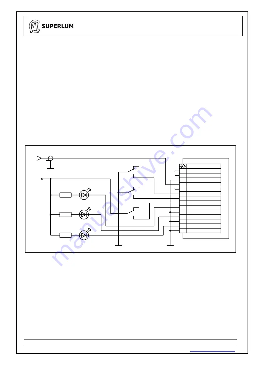
  Control  the  Light  Source  by  applying  control  signals  to  the  terminals  of  the  REMOTE  port.  Possible 

example is shown on Figure 3. More details about electrical connections to the REMOTE port can be found in 
Sec. 2.1 of the document. 
 

1K

+5V

1K

1K

RESERVED

REMOTE

RESERVED

HL3  SERVICE

HL1  OUTPUT ON

SERVICE STATUS

READINESS STATUS

OUTPUT STATUS

OUTPUT ON/OFF (N)

EXTERNAL MODULATION

SW2  ON/OFF

HL2  READY

XW1  MODULATION IN (0-5Vpp)

LOGIC GND

LOGIC GND

LOGIC GND

OUTPUT ON/OFF (P)

INTERLOCK CONTROL

IN5V (200 ohm)

EXTERNAL MODULATION GND

SW3  ON/OFF

SW1  INTERLOCK

13

11

10

8

6

4

2

14

12

9

7

5

3

1


Figure. 3 Example of basic controlling of the Light Source via REMOTE port 

 
4.4.6

  Uncheck  the 

“REMOTE CONTROL”

  box  of  the 

“SETTINGS”

  area  of  the  software  display  to disable 

the REMOTE port, and to return to manual controlling of the Light Source. 

Summary of Contents for OEM-MOPA

Page 1: ...EM Master Oscillator Power Amplifier SLD Light Sources User Manual ATTENTION ELECTROSTATIC SENSITIVE DEVICES SUPERLUM Diodes Ltd 2016 2020 All rights reserved B3 Fota Point Enterprise Park Carrigtwohi...

Page 2: ...SS 3R to 3B of IEC 60825 1 For further information regarding laser safety and laser classification of the Light Source please contact SUPERLUM Warranty Superlum products are guaranteed for a period of...

Page 3: ...ontrol Features 7 2 Technical Specification 8 2 1 Electrical Connections 8 2 2 General Specification 10 2 3 Fiber and Optical Connection Specification 10 2 4 Other Electro Optical Characteristics 10 3...

Page 4: ...mote port interfaces as standard options Please note that the OEM MOPA light source is intended for integration into the end user s equipment and is to be considered as an optical component For this r...

Page 5: ...kage Contents The OEM MOPA light source is coming with the following accessories as standard ones 1 x connector for the DC Power input port 1 x connector for the remote input port 1 x flat cable 0 5 m...

Page 6: ...er Manual Document ID SL 3328 01 000RE Rev 1 0 Date 25 09 2020 Page 6 of 23 SUPERLUM Diodes Ltd Ireland www superlumdiodes com 1 4 Outlines and Dimensions Figure 1 Drawings of Light Source Dimensions...

Page 7: ...al operation is disabled USB SERVICE mode LED reflects the status of the combined optical output i e all active SLD channels together that user pre selected in the companion software or all channels a...

Page 8: ...3 below There are three separate connectors ports first for 12V DC power supply second for REMOTE control external switching of SLDs on and off by analog signal triggering and remote interlock control...

Page 9: ...n to switching optical output ON 8 OUTPUT ON OFF P IN Allows switching the optical output Apply 5VDC voltage from external power supply between this pin and any LOGIC GND pin to switching optical outp...

Page 10: ...ble be less than 3m When installing the Light Source into an application where the 12 V DC power cable is over 3m Superlum advise that a ferrite of the type W rth 742 701 5 with 6 loops or similar is...

Page 11: ...e buyer user to design and certify any equipment incorporating any OEM source of Superlum to meet all local safety regulations prior to sale to the public The texts of these regulations are available...

Page 12: ...ation sensitive OSAs or OSAs with MM fiber optical inputs may disturb the measurement results i e introduce misbalances distortions and artifacts to measured spectral shapes 4 1 5 If no abnormality wa...

Page 13: ...ected optical output port IMPORTANT If discrepancies are found when comparing the observed optical output or spectrum to the ATR please contact SUPERLUM before further using the Light Source Using the...

Page 14: ...t or 2 GB 64 bit for Windows Vista and Windows 7 Processor 100 megahertz MHz or faster processor for Windows 9x and ME 300 MHz or faster processor for Windows 2000 and XP 1 gigahertz GHz or faster 32...

Page 15: ...Source 4 3 4 Brief description of software operation Run the software When starting the software for the first time the following window for selecting of COM port will appear If the drop down list fo...

Page 16: ...fore saving and e mailing the generated self test file The SETTINGS area of the software display allows the following control features Activate deactivate the remote interlock The interlock is activat...

Page 17: ...click USB MODE display button to toggle computer control on and off Manual control of the Light Source from the front device panel becomes disabled when the REMOTE CONTROL box has been checked on the...

Page 18: ...the process of device initialization assigning COM port It may take few minutes until the process will be completed Corresponding icon of the installer must appear in the system tray Upon completion o...

Page 19: ...ror message CR LF line termination sequence CR ASCII13 LF ASCII10 TYPE Light Source type five ASCII printable chars MOPA two channels Light Source VH Major part of firmware version 0 9 one ASCII chars...

Page 20: ...w for signal identification SIGNAL BIT DESCRIPTION OME 0 1 Optical module enabled 0 Optical module disabled TON 1 1 TEC ON 0 TEC OFF TGD 2 1 Optical module temperature stabilized 0 Optical module temp...

Page 21: ...optical module parameter read data from ADC Request U M CH PN CR LF Acknowledge U M CH PN ADATA CR LF Error message E CR LF common error message M CR LF wrong mode set message CH Channel number 1 2 o...

Page 22: ...0 ohm FFFF 65534 ohm 3 Optical module maximum current value 0000 270F four ASCII chars 0000 0 0 mA 270F 999 9 mA 4 Optical module current value 0000 270F four ASCII chars 0000 0 0 mA 270F 999 9 mA 5...

Page 23: ...Error message E CR LF common error message M CR LF wrong mode set message MN Optical module number 1 or 2 One ASCII character PN Parameter number 5 One ASCII character DATA Parameter data See table 2...

Reviews: