


OEM MOPA Light Sources. User Manual.
Document ID:
SL.3328.01.000RE / Rev. 1.0, Date: 25/09/2020 Page
16
of
23
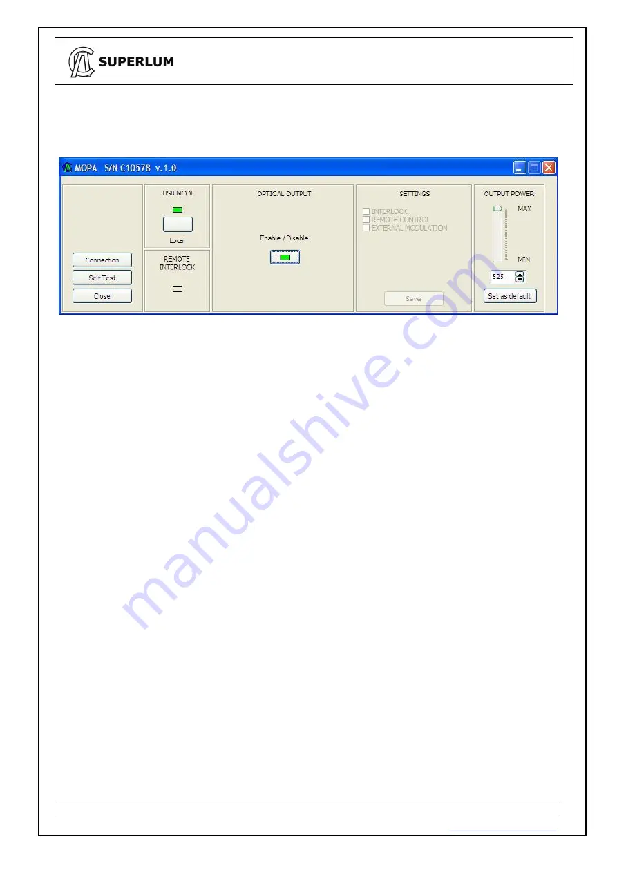
Once the
“USB MODE”
button has been clicked on the software display, the Light Source turns to remote
operation, and the following window appears (indicator turns from blank to green).
Manual control of the
Light Source from the front device panel becomes disabled once the Light Source has established computer
communication.
“Enable / Disable” display indicator in the
“OPTICAL OUTPUT”
area - show actual status of the optical
output. Optical output can be toggled on and off with the
“Enable / Disable” display button.
“Self Test”
option is used for internal self-testing of the Light Source
. It is initiated by clicking on the “
Self
Test
” display button. This procedure may take a few minutes after being initiated. Upon completion, the
program will automatically generate a test file, which should be e-mailed to SUPERLUM for further
processing and verification of actual device statuses. You can add your comments before saving and e-
mailing the generated self-test file.
The
“SETTINGS”
area of the software display allows the following control features:
-
Activate / deactivate the remote interlock.
The interlock is activated
– the optical output and all
controls become disabled, and the correspondent indicators (
“Remote” LED indicator on the device
panel, and
“REMOTE INTERLOCK” software display indicator) lit red – when the correspondent
control terminals on the REMOTE port are open circuited (see Sec. 2.1 for more details).
-
Activate /deactivate analog controls of the REMOTE
port (does not apply to the remote interlock
control, which is computer activated separately). Manual control of the Light Source remains disabled
when analog controls of the REMOTE port are activated.
-
Activate / deactivate the external modulation input.
Any changes to the
“SETTINGS”
area are possible only when the optical output is switched off. Changes are
applied immediately once correspondent boxes are ticked in the
“SETTINGS”
area.
To save changes introduced to the
“SETTINGS”
area, the
“Save”
display button in the
“SETTINGS”
area
must be clicked. In this case the introduced changes are stored even after device power re-setting.
Otherwise, the changes introduced are in place only during the current work session.


