background image

43

Chapter 5  

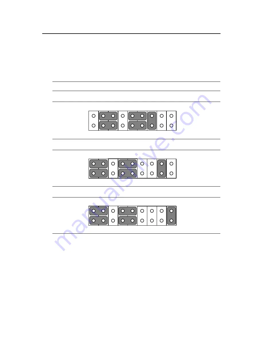
5.4  COM-port interface (JP4, JP5)

The panel PC provides two serial ports. COM1 (RS-232) and COM2 (RS-
232/422/485) in one COM port connector. 

5.4.1 COM2 RS-232/422/485 setting (JP4)

COM2 can be configured to operate in RS-232, RS-422, or RS-485 mode. 
This is done via JP6.

The IRQ and the address ranges for COM 1 and 2 are fixed. However, if 
you wish to disable the port or change these parameters later you can do 
this in the system BIOS setup. The table overleaf shows the default set-
tings for the panel PC’s serial ports.

Table 5.5: COM2 RS-232/422/485 setting (JP4)

*RS-232

RS-422

RS-485

* default setting

1

3

5

7

9

13

15

17

11

2

4

6

8

10

14

16

18

12

9

7

8

5

3

1

6

4

2

10

12

11

15 13

14

16

18

17

1

3

5

7

9

13

15

17

11

2

4

6

8

10

14

16

18

12

9

7

8

5

3

1

6

4

2

10

12

11

15 13

14

16

18

17

9

7

8

5

3

1

6

4

2

10

12

11

15 13

14

16

18

17

Summary of Contents for SL-PPC-154P4T

Page 1: ...SL PPC 154P4T Pentium 4 Processor Based Panel PC with 15 Color TFT LCD Display Users Manual ...

Page 2: ...edgements Award is a trademark of Award Software International Inc VIA is a trademark of VIA Technologies Inc IBM PC AT PS 2 and VGA are trademarks of International Business Machines Corporation Intel and Pentium are trademarks of Intel Corporation Microsoft Windows is a registered trademark of Microsoft Corp RTL is a trademark of Realtek Semi Conductor Co Ltd Winbond is a trademark of Winbond ele...

Page 3: ...till no guarantee that interference will not occur If this equip ment is believed to be causing harmful interference to radio or television reception this can be determined by turning the equipment on and off If interference is occurring the user is encouraged to try to correct the inter ference by one or more of the following measures Reorient or relocate the receiving antenna Increase the separa...

Page 4: ... Floppy disk with CD ROM drive driver Drivers and Utilities CD ROM disc Heat sink optional refer to Notes 1 and 2 below If any of these items are missing or damaged contact your distributor or sales representative immediately Note1 If the unit you have bought is basic i e without a CPU HDD or SDRAM you will find this optional item in the accessory box Note2 If you install an Intel processor yourse...

Page 5: ...name and serial number Description of your peripheral attachments Description of your software operating system version application software etc A complete description of the problem The exact wording of any error messages Warning 1 Input voltage rated 100 240 VAC 50 60 Hz 4 A 2 Use a 3 V 195 mA lithium battery 3 Packing please carry the unit with both hands handle with care 4 Maintenance to prope...

Page 6: ...r any liquid into an opening This may cause fire or electrical shock 13 Never open the equipment For safety reasons the equipment should be opened only by qualified service personnel 14 If one of the following situations arises get the equipment checked by service personnel a The power cord or plug is damaged b Liquid has penetrated into the equipment c The equipment has been exposed to moisture d...

Page 7: ...g vermieden 12 Durch die Lüftungsöffnungen dürfen niemals Gegenstände oder Flüssigkeiten in das Gerät gelangen Dies könnte einen Brand bzw elektrischen Schlag aus lösen 13 Öffnen Sie niemals das Gerät Das Gerät darf aus Gründen der elektrischen Sicherheit nur von authorisiertem Servicepersonal geöffnet werden 14 Wenn folgende Situationen auftreten ist das Gerät vom Stromnetz zu trennen und von ein...

Page 8: ...SL PPC 154P4T User s Manual viii ...

Page 9: ...3 Switching on the power 14 2 4 Running the BIOS Setup Program 15 2 5 Installing System Software 16 2 6 Installing the Drivers 17 Chapter 3 Using the Panel PC 20 3 1 Introduction 20 3 2 Floppy drive 20 Figure 3 1 Inserting and ejecting a floppy disk 20 3 3 CD ROM Drive 21 Figure 3 2 Inserting and ejecting a CD ROM 21 3 4 Multi card Reader 22 Figure 3 3 Opening the card reader s door 22 Figure 3 4 ...

Page 10: ...ral Processing Unit CPU 33 4 5 Installing the DDR SDRAM Memory Module 35 Figure 4 10 Placing the memory module in the DIMM35 Chapter 5 Jumper Settings Connectors 38 5 1 Jumpers and Connectors 38 5 1 1 Setting jumpers 38 5 1 2 Jumpers and switches 39 Table 5 1 Jumpers switches and their functions 39 5 1 3 Jumper Locations 39 Figure 5 1 Jumpers on the PPC 153 motherboard 39 5 1 4 Connectors 40 Table...

Page 11: ...1 ATX Power connector 1 CN1 50 Table A 1 AT Power connector 1 CN1 50 A 2 ATX power connector 2 CN2 51 Table A 2 ATX power connector 2 CN2 51 A 3 LVDS connector 1 CN4 51 Table A 3 LVDS connector 1 CN4 51 A 4 LVDS connector 2 CN6 52 Table A 4 Table B 4 LVDS connector 2 CN6 52 A 5 Inverter power connector CN5 52 Table A 5 Inverter power connector CN5 52 A 6 FDD connector CN9 53 Table A 6 FDD connecto...

Page 12: ...PPC 153 User s Manual xii ...

Page 13: ...CHAPTER 1 General Information This chapter gives background information on the SL PPC 154P4T panel PC Sections include Introduction Specifications Dimensions ...

Page 14: ...board Intel Pen tium 4 CPU up to 3 06 GHz HT Technology support memory up to 2 GB DDR SDRAM the Intel 845GV chipset and an onboard PCI Ethernet controller Multimedia devices connectors and one PCI socket is available for expansion There are multi COM port interfaces and five main extensions a built in CD ROM drive CompactFlash socket FDD two PCMCIA Type II slots and four USB 2 0 ports An optional ...

Page 15: ...45GV ICH4 2nd level cache On die 256 or 512 KB RAM Two 184 pin DDR DIMM sockets up to 2GB DDR SDRAM PCI bus master IDE interface Supports two connectors Each con nector has one channel and supports two IDE devices Each channel supports PIO modes 0 4 DMA mode 0 2 and Ultra DMA 33 66 100 simultaneously The secondary connector is designated for the CD ROM drive BIOS supports IDE CD ROM boot up Floppy...

Page 16: ...lay type Simultaneously supports CRT and flat panel displays EL LCD and gas plasma Display resolution Supports non interlaced CRT and TFT LCD dis plays up to 1024 x 768 256K Audio function Chipset Integrated in Intel 845GV ICH4 South Bridge Audio controller AC97 Ver 2 0 compliant interface Multi stream Direct sound and Direct Sound 3D acceleration Stereo sound 18 bit full duplex codec Audio interf...

Page 17: ...terface Complies with 1995 PCMCIA card standard Supports two PCMCIA card CardBus slots Two sockets support both a 16 bit PCMCIA card and a 32 bit CardBus simultaneously Hot insertion and removal Card Reader Optional kit for multiple readable cards including Memory stick MS pro Security Disk SD Multimedia Card MMC Compact Flash CF Type 1 Type2 Smartmedia SM Type Analog Resistive Capacitive Surface ...

Page 18: ...45 C 32 122 F Relative humidity 10 95 40 C non condensing Shock 10 G peak acceleration 11 msec duration Power MTBF 100 000 hrs Certifications EMC CE FCC VCCI BSMI approved Safety CE CAS UL CB 1 3 Dimensions Figure 1 1 Dimensions of the SL PPC 154P4T Units mm ...

Page 19: ...ter details system setup on the SL PPC 154P4T panel PC Sections include A Quick Tour of the Panel PC Preparing for First time Use Installation Procedures Running the BIOS Setup Program Installing System Software Installing the Drivers ...

Page 20: ...up the panel PC take a moment to become familiar with the locations and purposes of the controls drives connectors and ports which are illustrated in the figures below When you place the panel PC upright on the desktop its front panel appears as shown in Figure 2 1 Figure 2 1 Front view of SL PPC 154P4T panel PC ...

Page 21: ...side panel cover The sunken I O section is at the bottom of the panel PC as shown in Fig 2 3 The I O section includes various I O ports including serial ports parallel port the Ethernet port USB ports the microphone jack and so on Figure 2 3 Rear view of the panel PC CD ROM Eject Button PCMCIA Socket Cardreader Optional Floppy Drive PCMCIA Eject Button S Video Lin e in Line ou t Mic in IEEE 1394 x...

Page 22: ... 100 240 volts 50 60 Hz Be sure to always handle the power cords by hold ing the plug ends only Follow these procedures in order 1 Connect the female end of the power cord to the AC inlet of the panel PC 2 Connect the 3 pin male plug of the power cord to an electrical out let 2 3 2 Connecting the keyboard and mouse Connect the PS 2 mouse and keyboard to the I O section of PPC If you use a serial m...

Page 23: ... either when you turn on or reset the panel PC by pressing the Del key on your keyboard immediately after powering on the computer The settings you specify with the setup program are recorded in a special area of memory called CMOS RAM This memory is backed up by a bat tery so that it will not be erased when you turn off or reset the system Whenever you turn on the power the system reads the setti...

Page 24: ... 2 Refer to Chapter 12 if you wish to change the BIOS settings Power on your panel PC or reset the system by pressing the Ctrl Alt Del keys simultaneously The panel PC will automati cally load the operating system from the diskette or CD ROM If you are presented with the opening screen of a setup or installation pro gram follow the instructions on screen The setup program will guide you through pr...

Page 25: ... ing prompt is displayed on screen A INSTALL Press Enter and the installation process will be completed in a few sec onds The standard procedures for installing the VGA Chipset Software Audio ICH4USB2 0 Ethernet touchscreen and Card reader drivers are described in Chapter 6 The various drivers and utilities in the CD ROM disc have their own text files which help users install the drivers and under...

Page 26: ...SL PPC 154P4T User s Manual 18 ...

Page 27: ...4T panel PC hardware Sections include Introduction Floppy Drive CD ROM Drive PCMCIA PS 2 Mouse and Keyboard PCI ISA Bus Expansion Parallel Port Serial COM Ports VGA Port Game Port USB Ports Audio Interface Ethernet Adjusting the LCD Contrast and Brightness Touchscreen optional ...

Page 28: ...d between your thumb and your other fingers and push it toward the drive See Fig 3 1 Slide the disk until it clicks into place To eject a floppy disk first make sure that the drive activity light is off and then press the eject button on the drive When the disk pops out of the drive remove it and store it properly Figure 3 1 Inserting and ejecting a floppy disk Note New disks must be formatted by ...

Page 29: ...d See Fig 3 2 Align the center hole of the CD ROM disc with the center circle of the CD ROM holding plate Press the transparent ring around the center hole of the CD ROM until you hear a click Push the front panel of the CD ROM drive back to its original place To eject a CD ROM disc first ensure that the drive activity light is off Then press the eject button on the drive When the disc pops out of...

Page 30: ...me Flash Memory cards must be prepared by your operating system before you can use them for data storage See your Flash Memory card manual for details To eject a Flash Memory card first ensure that the panel PC is not access ing the memory card or device Then press the appropriate eject button on the socket When the card pops out of the socket remove it and store it properly Figure 3 3 Opening the...

Page 31: ...the panel PC 3 6 PCI Bus Expansion The panel PC supports PCI bus expansion cards To integrate a new PCI bus card into your system follow these instructions 1 Turn off the panel PC 2 Unscrew the eight screws on the top of the rear cover and remove it 3 Remove the metal plate by unscrewing the single attaching screw 4 Insert the PCI bus card into the PCI slot of the riser card See Fig 3 6 overleaf 5...

Page 32: ...am to configure the parallel port to respond as required by your printer and software operating environment 3 8 Serial COM ports There are four serial COM ports on the bottom of the rear cover You can easily attach a serial device to the panel PC such as an external modem or mouse Follow these instructions 1 Be sure the panel PC and any other peripherial devices you may have connected to the panel...

Page 33: ...nected to the system through the 15 pin external port located on the rear of the system unit 1 Be sure the panel PC is turned off 2 Connect the external joystick or game device to the system See Fig 3 5 3 Turn on the panel PC and the external joystick or game device if applicable 4 Install the driver before you use the joystick or game device 3 11 USB Ports An external USB device may be connected ...

Page 34: ... sure the panel PC is turned off 2 Connect the external device s to the panel PC See Fig 3 4 3 Turn on the panel PC and the external device s 4 Under DOS run the RSET8139 program to check the hardware network status before installing the Ethernet driver 5 Run the Ethernet driver to connect up to the network 3 14 Touchscreen Optional The touchscreen is connected to the internal USB port Its functio...

Page 35: ...pherals switches and indicators Be sure to read all the safety precautions before you begin the installation proce dures Sections include Jumpers and Connectors Disassembling the Panel PC Installing the 2 5 Hard Disk Drive HDD Installing the Central Processing Unit CPU Installing the SDRAM Memory Module Installing the Floppy Disk Drive FDD and Slim CD ROM Drive ...

Page 36: ...d shielding case Any maintenance or hardware upgrades can be easily completed after removing the rear panel and shielding case If you are a systems integrator and need to know how to completely dis assemble the panel PC you can find more useful information in Appen dix B Warning Do not remove the plastic rear cover until you have verified that no power is flowing within the panel PC Power must be ...

Page 37: ... are illustrated in Fig 4 1 4 2 4 3 and 4 4 1 Unscrew the three screws that secure the plastic side cover and then remove it Figure 4 1 Unscrew the screw of side cover 2 Unscrew the eight screws that secure the plastic rear cover and then remove it Make sure the rear cover is removed from the right side first Figure 4 2 Unscrewing rear cover of the panel PC ...

Page 38: ... to remove it Figure 4 3 Opening the rear cover Figure 4 4 The PPC without the Rear Cover 4 Unscrew the four screws that secure the CPU cover 5 Remove the floppy drive HDD and CD ROM cables then remove the side panel 6 Unscrew the ten screws of the shielding case and remove it ...

Page 39: ...e panel PC s internal controller which uses a PCI local bus interface The advanced IDE controller supports faster data transfer and allows the IDE hard drive to exceed 528 MB The following are instruc tions for installation Figure 4 5 Screw the HDD metal frame to the side of the HDD Figure 4 6 Place the HDD frame so it fits with the studs ...

Page 40: ...SL PPC 154P4T User s Manual 32 Figure 4 7 Plug the EIDE cable into the HDD Figure 4 8 Screw the right side of the metal plate to fix it Figure 4 9 Screw the left side of the metal plate to fix it ...

Page 41: ...he connector which is labeled on the board Plug the other end of the cable into the IDE hard drive with Pin 1 on the cable corresponding to Pin 1 on the hard drive 4 4 Installing the Central Processing Unit CPU The panel PC s central processing unit CPU can be upgraded to improve system performance The panel PC provides one 478 pin ZIF Zero Inser tion Force socket Socket 478 The CPU must come with...

Page 42: ...SL PPC 154P4T User s Manual 34 1 Lift up the ZIF 2 Place the CPU carefully into the socket 3 Attach the heatsink and fan on top of the CPU and fasten them with the retention bracket ...

Page 43: ...or FAN1 4 5 Installing the DDR SDRAM Memory Module You can install from 64 MB to 2 GB of DDR SDRAM memory The panel PC system provides two 184 pin DIMM Dual Inline Memory Module socket and supports 2 5 V DDR SDRAM Figure 4 10 Placing the memory module in the DIMM ...

Page 44: ...SL PPC 154P4T User s Manual 36 ...

Page 45: ...rs and connecting peripherals switches and indicators Be sure to read all the safety precautions before you begin the installation proce dures Sections include Jumpers and Connectors CPU Installation CMOS Clear for External RTC JP8 COM port Interface Internal 12 V Source Selection Set ting JP1 VGA Interface Watchdog Timer Configuration ...

Page 46: ...hem To close a jumper you connect the pins with the clip To open a jumper you remove the clip Sometimes a jumper will have three pins labeled 1 2 and 3 In this case you would connect either pins 1 and 2 or pins 2 and 3 The jumper settings are schematically depicted in this manual as follows A pair of needle nose pliers may be helpful when working with jumpers If you have any doubts about the best ...

Page 47: ...s the function of each of the board s jumpers 5 1 3 Jumper Locations Figure 5 1 Jumpers on the PPC 153 motherboard Table 5 1 Jumpers switches and their functions Label Function JP1 FSB Front Side Bus Setting JP2 LCD Power Setting JP3 Clear CMOS JP4 COM2 RS232 422 485 jumper setting JP5 COM1 COM2 pin 9 output type setting JP6 PS2 Interface for touchscreen SW1 Panel type setting 1 ...

Page 48: ...ctors Table 5 2 Panel PC connectors Label Function CN1 ATX 20 pin power connector CN2 ATX 12V Power connector CN4 LVDS connector 1 CN5 Invertor Power connector 2 CN6 LVDS connector 2 CN9 FDD Connector CN15 Internal Speaker Connector CN16 EIDE HDD connector CN17 CD ROM Connector CN24 IR connector CN25 USB4 5 connector FAN1 CPU fan power connector FAN2 System fan power connector PCI1 PCI1 PCI bus ex...

Page 49: ...41 Chapter5 5 1 5 Locating connectors Figure 5 2 Connectors on PPC 153 motherboard ...

Page 50: ...1 Turn off system 2 Short pin 2 and pin 3 3 Return jumper to pins 1 and 2 4 Turn on the system The BIOS is now reset to its default setting Warning To avoid damaging the computer always turn off the power supply before setting Clear CMOS Set the jumper back to Normal operation before turning on the power supply Table 5 3 Front Side Bus Setting JP1 Decided by CPU Select 100 MHz Select 133 MHz Table...

Page 51: ...and 2 are fixed However if you wish to disable the port or change these parameters later you can do this in the system BIOS setup The table overleaf shows the default set tings for the panel PC s serial ports Table 5 5 COM2 RS 232 422 485 setting JP4 RS 232 RS 422 RS 485 default setting 1 3 5 7 9 13 15 17 11 2 4 6 8 10 14 16 18 12 9 7 8 5 3 1 6 4 2 10 12 11 15 13 14 16 18 17 1 3 5 7 9 13 15 17 11 ...

Page 52: ...D and active LCD displays 5 5 1 LCD panel power setting The panel PC s AGP SVGA interface supports 5 V and 3 3 V LCD dis plays The LCD cable already has a built in default setting You do not need to adjust any jumper or switch to select the panel power Default setting Table 5 6 COM 1 2 Pin 9 setting JP5 Select 5 V Select Ring default setting Table 5 7 LCD Panel Power Setting JP2 Select 5V Select 3...

Page 53: ...ver Installation This chapter provides information on how to install the drivers for SL PPC 154P4T Sections include Introduction Installation of SL PPC 154P4T driver for Windows 98 NT 2000 ME XP Further Information ...

Page 54: ... dual channel DMA engine includes UltraDMA 33 66 100 and interlaced dual channel commands 6 2 Driver Installation Before installing the Ethernet driver note the procedures below You must know which operating system you are using in your SL PPC 154P4T and then refer to the corresponding installation flow chart Then just follow the steps described in the flow chart You will quickly and successfully ...

Page 55: ...ation of Card reader D SL PPC 154P4T Cardreder drivers winxxxx setup exe 6 2 6 Software installtion of software for Cardreader D SL PPC 154P4T Cardreader Flashdoctor exe 6 2 7 Software Installation for Chipset IAA Driver D SL PPC 154P4T chiupset software IAA Driver 2 3 iaa23_multi exe INF Driver D SL PPC 154P4T chiupset software INF Driver 4 30 1006 infinst auto1 exe 6 2 8 Driver installation of t...

Page 56: ... For further information about the AGP VGA installation in your PPC 153 including driver updates troubleshooting guides and FAQ lists visit the following web resources VIA website www via com tw SuperLogics websites www SuperLogics com www SuperLogics com tw ...

Page 57: ...Appendix A Pin Assignments ...

Page 58: ...x A Pin Assignments A 1 ATX Power connector 1 CN1 Table A 1 AT Power connector 1 CN1 Pin Signal Pin Signal 1 3 3V 11 3 3V 2 3 3V 12 12V 3 GND 13 GND 4 5V 14 PS ON 5 GND 15 GND 6 5V 16 GND 7 GND 17 GND 8 PW OK 18 5V 9 5VSB 19 5V 10 12V 20 5V ...

Page 59: ...TX power connector 2 CN2 Pin Signal Pin Signal 1 GND 3 12V 2 GND 4 12V Table A 3 LVDS connector 1 CN4 Pin Signal Pin Signal 1 VDD 11 RXIN2 2 VDD 12 RXIN2 3 GND 13 GND 4 GND 14 RXIN1 5 RXIN3 15 RXIN1 6 RXIN3 16 GND 7 GND 17 RXIN0 8 CLK0 18 RXIN0 9 CLK0 19 DDC_CLK 10 GND 20 DDC_DAT ...

Page 60: ...able B 4 LVDS connector 2 CN6 Pin Signal Pin Signal 1 VDD 11 RXIN6 2 VDD 12 RXIN6 3 GND 13 GND 4 GND 14 RXIN5 5 CLK1 15 RXIN5 6 CLK1 16 GND 7 GND 17 RXIN4 8 RXIN7 18 RXIN4 9 RXIN7 19 CONTRAST 10 GND 20 HPLG_DT Table A 5 Inverter power connector CN5 Pin Signal 1 12V 2 GND 3 ENABKL 4 Brightness Adj 5 5V ...

Page 61: ...Pin Signal 1 Vcc 5V 14 Step 2 Index 15 GND 3 Vcc 5V 16 Write data 4 Drive select 17 GND 5 Vcc 5V 18 Write enable 6 Disk change 19 GND 7 NC 20 Track 0 8 NC 21 GND 9 NC 22 Write protect 10 Motor on 23 GND 11 NC 24 Read data 12 Direction 25 GND 13 Density select 26 Side 1 select ...

Page 62: ... Fan power connector FAN1 FAN2 Table A 7 Internal speaker connector CN15 Pin Signal 1 Speaker out_R 2 Speaker out_R 3 Speaker out_L 4 Speaker out_L Table A 8 IR connector CN24 Pin Signal 1 Vcc 2 NC 3 IR_IN 4 GND 5 IR_OUT Table A 9 Fan power connector FAN1 FAN2 Pin Signal 1 GND 2 12V 3 FAN_DET ...

Page 63: ...Appendix B Full Disassembly Procedure ...

Page 64: ...ity whatsoever for any problems or damage caused by the user disassembly of the panel PC Make sure the power cord of the panel PC is unplugged before you start disassembly The following procedures do not include the detailed disassembly proce dures for the CPU HDD CD ROM drive FDD and SRAM all of which can be found in Chapter 4 1 Unscrew the screws of the side cover 2 Unscrew the screws of the rea...

Page 65: ...57 AppendixB 3 Lift the right side of the rear cover first to remove it 4 The PPC without the rear cover 5 Unscrew the board of the card reader ...

Page 66: ...SL PPC 154P4T User s Manual 58 6 Unscrew the screw of PCI extension bus card away from PCI slot 7 Lift out the metal plate of the I O shield from the I O 8 Lift out FPC cable from the FDD ...

Page 67: ...59 AppendixB 9 Lift out the cable from the CD ROM 10 Unscrew the two screws of the bottom side to loosen the metal plate of CD ROM FDD module 11 unscrew the otherside of the metal plate ...

Page 68: ...SL PPC 154P4T User s Manual 60 12 Unscrew the screws to loosen the CD ROM and FDD from mod ule 13 Lift the FDD from the module 14 Unscrew the screws from the side of the module to loosen the CD ROM ...

Page 69: ...61 AppendixB 15 Lift up the ATX 20 pins power connector 16 Lift up the ATX 12V 4 pins power connector 17 Lift up the EIDE cable from mainboard ...

Page 70: ...SL PPC 154P4T User s Manual 62 18 Loosen the screws from the bottom for remove the power module 19 Loosen the screws to lift up the board ...

Reviews: