background image

NOTE: DIAGRAMS & ILLUSTRATIONS ARE NOT TO SCALE.

19

GAS CONTROL MODULE SYSTEM 

REMOTE CONTROL FEATURE

The module has a built in remote control receiver that allows the user 

to program the remote transmitter at any time during or after the instal-

lation of the burner.

1.  There is a switch located on the right side of the module that reads 

REMOTE/OFF (

Figure 29

).

2. When the remote/off switch is in the OFF position, the burner will 

operate from the rocker switch that is mounted near the module 

(

Figure 29A

and connected to the brown switch wires. 

3.  When the remote/off is in the REMOTE position the burner will operate 

from the Remote Control Transmitter.

NOTE:

 The module must be programmed to the Remote Control Trans-

mitter.

•  To program the module (make sure the system has power), locate 

the learn button (

Figure 30

) on the module. Locate the metal shield 

that is covering the module and remove the screw on top. Use a 

small thin object like a paper clip (not sharp points) to press and 

release the learn button. There will be a beep sound from the module. 

Then press any button on the remote transmitter. Once the module's 

internal receiver accepts the transmitter code, there will be a series 

of confirming beeps. 

•  The remote system is ready for use.

•  Pushing and holding the LEARN button for 6 seconds will result in 

clearing the transmitter security code from the module's memory. 

The module will make three long beeps in succession when it has 

been cleared.

REMOTE CONTROL "DRY-OUT" FEATURE

The remote/Ignitor has a special feature. It will allow heat from the burner 

to dry the probe and burner assembly due to excess moisture, caused 

by rain, humidity or condensation. To activate:

•  Press and hold the HI and LO buttons on the transmitter for 30-45 

seconds. This allows the sparking to start and the burner to ignite. 

•  Release the HI and LO buttons, after the allotted time, sparking will 

stop and the burner will go out. 

•  Press and hold the ON button and sparking will start again and 

burner should ignite. 

•  Release the ON button. The sparking will stop, and the burner 

should stay ON. 

•  Repeat if necessary.

Remote/Off Switch

ADJ.

“S” Pilot Connection

“I” Pilot Connection

AF-4000 MOD Module Rt Side


Figure 29 - Gas Module Right Side


AF-4000 MOD  Module Lt Side

AUX Connection

Learn Button


Figure 30 - Gas Module Left Side

Figure 29A - Rocker Switch

Rocker Switch 

(for burner)

REPLACEMENT PARTS

NOTE:

 Use only original replacement parts. This will protect your 

warranty coverage for parts replaced under warranty.
Normally, all parts should be ordered through your IHP distributor 

or dealer. Parts will be shipped at prevailing prices at time of order.

NEVER USE SUBSTITUTE MATERIALS. USE OF NON-APPROVED 

PARTS CAN RESULT IN POOR PERFORMANCE AND SAFETY 

HAZARDS.

TECHNICAL SERVICE
You may have further questions about installation, operation, or 

troubleshooting. Please contact your IHP dealer for any questions 

or concerns. When contacting your dealer please have your model 

and serial numbers of your appliance ready. You can also visit our 

web site at SuperiorFireplaces.us.com

Summary of Contents for VRE3236ZENWH

Page 1: ...If you cannot reach your gas supplier call the fire department Installation and service must be performed by a qualified installer service agency or the gas supplier DANGER FIRE OR EXPLOSION HAZARD Failuretofollowsafetywarningsexactlycouldresult in serious injury death or property damage AVERTISSEMENT RISQUED INDENDIE OU D EXPLOSION Le non respect Des avertissements de sécurité pourrait d entraîne...

Page 2: ...iance and CAN 1 2 21 M85 standard for gas fired appliance for outdoor installation TheInstallationmustconformtolocalcodesor in the absence of local codes with the National Fuel Gas Code ANSI Z223 1 NFPA 54 or the Natural Gas and Propane Installation Code CAN CGA B149 1 or Propane Storage and Handling Code B149 2 as applicable The appliance when installed must be electri cally grounded in accordanc...

Page 3: ...lled in accordance with 527 CMR 30 Installation and repair must be done by a plumber or gas fitter licensed in the Commonwealth of Massachusetts The flexible gas line connector used shall not exceed 36 inches 92 centime ters in length The individual manual shut off must be a T handle type valve Unvented appliances may NOT be in stalled in bedrooms or bathrooms A working smoke detector must be in s...

Page 4: ...e Waterproofing The Fireplace and Figure 2 on Page 5 3 Plumb gas line Gas connections should only be performed by an experienced licensed certified tradesman 4 Complete the installation finish wall mate rial surround and hearth extension to your individual taste 5 Assemble and attach optional accessories Study the three dimensional illustration Fig ure 5 Page 7 to get a general idea of each elemen...

Page 5: ...ireplaceonitslocation Figure 2 Step 2 Ontheexposeddrainhole installaPVC threaded coupling reducer 3 4 x 1 2 going from the top of the pan down through the hole Apply a silicone based sealant around the base and threads before installation Step 3 Holding the reducer coupling with a wrench thread a 3 4 90 degree PVC elbow to the reducer until it is tight to the metal Step 4 Addadditionalpipingtorout...

Page 6: ... shall not open directly above a sidewalk or paved driveway which is located between two single family dwellings and services both dwellings Only permitted if veranda porch deck or balcony is fully open on a minimum of 2 sides beneath the floor or if the screened porch guidelines are followed Note 1 Local codes or regulations may require different clearances Note 2 Fireplaces in an alcove space sp...

Page 7: ...e If a wall covering such as Durock is to be attached to the rear wall then the depth must be measured from the wall surface It is important that this dimension be exact NOTE Non combustibleframingmembersare not required but are recommended Figure 5 TYPICAL INSTALLATION CAUTION If propane is used be aware that with a tank that is too small i e under 100 lbs if this is the only gas appliance in the...

Page 8: ...es millimeters Model No A B C 37 940 41 3 4 1061 23 1 2 597 43 1092 47 3 4 1213 29 1 2 749 1 3 4 28 1 2 724 41 3 8 1051 34 1 4 870 5 127 20 508 12 305 4 3 8 111 Left Side Gas Inlet 8 1 4 210 2 51 Model Ship Weight lbs Shipping Volume 230 lbs 38 Cu Ft Weight And Volume 200 lbs 35 Cu Ft Polaris36 Polaris42 Polaris36 Polaris42 Model Ship Wt Shipping Volume VRE3236 260 lbs 28 424 Cu Ft VRE3242 290 lbs...

Page 9: ...crease Framing Height by 34 when using an Optional Drain Pan inches millimeters 12 305 10 254 8 203 6 152 4 102 2 51 9 229 13 330 11 280 15 381 13 330 17 432 15 381 19 483 17 432 21 534 19 483 23 585 Hood Fireplace Fireplace Mantel depth Mantel depth WITHOUT HOOD INSTALLED WITH HOOD INSTALLED Top of Firebox Opening 12 305 10 254 8 203 6 152 4 102 2 51 Mantel Clearances Opening VRE3236 VRE3242 A 42...

Page 10: ...ality Instal lation must be in compliance with local codes These appliances are equipped with a gas flex line for use where permitted in connecting the unit to the gas line A gas flex line is provided to aid in attaching the outdoor appliance to the gas supply The gas flex line can only be used where local codes permit See Figure 12 for flex line description The flex line is rated for both natural...

Page 11: ...o the appliance before you install grate and logs This appliance is not designed to burn wood Any attempt to do so could cause irreparable damage to appliance and prove hazardous If the logs are not installed according to these instructions improper combustion could occur This could result in the excessive production of soot and or the colorless odorless toxic gas carbon monoxide CO The size and p...

Page 12: ...e Twig Log 7 Top Rear Log 8 Top Left Log 1 Place rear log 1 being pilot in between the tube burner Figure 15 2 Place middle log 2 directly in front of tube burner Figure 16 3 Place front right log 3 onto grate The notch on the charred section will fit around the grate Figure 17 4 Place front left log 4 onto grate The notch on the charred section will fit around the grate Figure 18 Top View Top Vie...

Page 13: ... middle log 2 Figure 22 Installing the VRE3200 Series Log Set continued Figure 19 Place Top Right Log 5 Figure 20 Place Middle Twig Log 6 5 6 7 8 1 1 2 2 3 3 4 4 5 Top View Top View Top View Top View Bottom View Bottom View Bottom View Bottom View 1 2 3 4 5 6 1 2 3 4 5 6 7 Figure 21 Place Top Rear Log 7 Figure 22 Place Top Left Log 8 Landing for Log 8 Protrusion for Log 8 Cut out fits over protrus...

Page 14: ...ent to the face opening These appliances should not smoke Small amounts of soot will accumulate over time and should be expected This soot adds to the realism of the firebox interior The logs can be cleaned when cool with a soft brush and small amounts of water Keep in mind that this is an outdoor appli ance Wind and air currents cannot be strictly controlled If the flame acts too erratically we r...

Page 15: ...ctronic Appliance Checkout Carbon Monoxide Poisoning Early signs of carbon monoxide poisoning are similar to the flu with headaches dizziness and or nausea If you have these signs obtain fresh air immediately Turn off the gas sup ply to the appliance and have it serviced by a qualified professional as it may not be operating correctly Figure 24 Clearances To Combustibles 6 153 Minimum For Combusti...

Page 16: ...e risque d incendie d explosionoulaproductiondemonoxydedecarbonepouvant causer des dommages matériels des blessures ou la mort Le tecnicien agrééestresponsabledel installationdecettetrousse L installationn est pas adéquate ni complète tant que le bon fonctionnement de l appareil convertin apasétévérifiéselonlesinstructionsdufabricantfourniesavec la trousse Le fournisseur de service qualifié ayant ...

Page 17: ...LURETOCOMPLYWITHTHEINSTAL LATIONANDOPERATINGINSTRUCTIONS PROVIDED IN THIS DOCUMENT WILL RESULTINANIMPROPERLYINSTALLED AND OPERATING APPLIANCE VOIDING ITS WARRANTY ANY CHANGE TO THIS APPLIANCE AND OR ITS OPERATING CONTROLSISDANGEROUS IMPROPER INSTALLATION OR USE OF THIS APPLI ANCE CAN CAUSE SERIOUS INJURY OR DEATHFROMFIRE BURNS EXPLOSION OR CARBON MONOXIDE POISONING AVERTISSEMENT SURVEILLER LES ENF...

Page 18: ...per ignition of the burner Alterations may have occurred during shipping and handling Call a qualified service person to readjust the igniter assembly if necessary The igniter should be positioned as shown in Figure 28 NOTE Figure 28 shows the correct positioning of the igniter and sensing rod If your igniter assembly does not meet these requirements Turn appliance off see To Turn Off Gas to Appli...

Page 19: ...sion when it has been cleared REMOTE CONTROL DRY OUT FEATURE The remote Ignitor has a special feature It will allow heat from the burner to dry the probe and burner assembly due to excess moisture caused by rain humidity or condensation To activate Press and hold the HI and LO buttons on the transmitter for 30 45 seconds This allows the sparking to start and the burner to ignite Release the HI and...

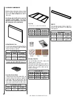
Page 20: ...rse weather Hood Kit This attractive brushed stainless Hood Kit is easy to install and enhances the appearance of the appliance Decorative Volcanic Stone Thedecorativevolcanicstone ModelFDVS can be used to enhance the look of your appliance Order model FDVS for replacement of stone when needed Spread the decorative volcanic stone evenly around the bottom ofthe firebox Cannot be used with 36 42LBFO...

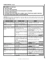
Page 21: ...r Immediately call a qualified service technician to inspect the appliance and to replace any part of the control system and any gas control which has been under water LIGHTING INSTRUCTIONS TO TURN OFF GAS TO APPLIANCE 1 STOP Read the safety information first 2 Do not attempt to light the burner by hand 3 Turn equipment shutoff valve clockwise to the OFF position see Figure 31 Do not force 4 Wait ...

Page 22: ...ment shutoff valve 2 Repeat igniting operation until air is removed 3 Contact local propane LP gas company 4 Set control module to REMOTE position 5 Contact qualified service person to check pres sure 6 Contact local natural or propane LP gas company 7 Clean burner see Cleaning and Maintenance Page 18 or replace burner orifice s 8 See Wiring Diagram Page 24 9 Verify black ground wire from module i...

Page 23: ... If noise is excessive contact qualified service person 2 Check igniter position and adjust if needed See Figure 28 Page 18 3 Should wind disturb the burner flame the igniter will automatically spark to relight the burner This is normal when the appliance is installed outdoors in windy conditions 4 Check wiring connections see wiring diagram Page 24 Replace wire harness if necessary Appliance prod...

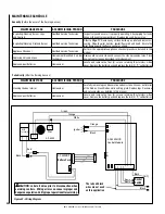
Page 24: ... Page 17 Remove any surface build up on pilot and burner as sembly Wipe the pilot nozzles igniter flame rod and hood Ensure the pilot flame engulfs the flame sensor as shown Appliance Checkout Qualified Service Technician Perform the appropriate appliance checkout procedure detailed in this manual Replacing Volcanic Stone Homeowner Qualified Services Technician Remove old volcanic stone and vacuum...

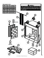
Page 25: ...236ZEPWS 36 White Stacked LP F4121 VRE3236ZEPWH 36 White Herringbone LP Cat Model Description F4122 VRE3242ZENWS 42 White Stacked NG F4123 VRE3242ZENWH 42 White Herringbone NG F4124 VRE3242ZEPWS 42 White Stacked LP F4125 VRE3242ZEPWH 42 White Herringbone LP 5 4 WARNING Contact an IHP dealer to obtain any of these parts Never use substitute materials not approved by IHP Use of non approved parts ca...

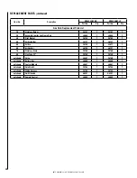
Page 26: ...935 1 H4936 1 12 Corner Post LH H4937 1 H4937 1 13 Corner Post RH H4938 1 H4938 1 14 Stand Off Bracket H2716 4 H2716 4 15 Cover Plate Gas Access H4955 1 H4955 1 16 Log Set F0114 1 F0114 1 17 Screen H4926 2 H4927 2 18 Screen Rod H4939 2 H4940 2 22 Flex Connector 93L32 2 93L32 2 23 Volcanic Stone Not Pictured 80L42 3 80L42 3 WARNING Never use substitute materials Use of non approved parts can result...

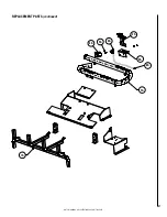
Page 27: ...NOTE DIAGRAMS ILLUSTRATIONS ARE NOT TO SCALE 27 REPLACEMENT PARTS continued 2A 3A 8A 1A 4A 5A 6A 7A ...

Page 28: ...8 1 3A Pilot Bracket F4152 1 F4152 1 4A Orifice Holder J6127 1 J6127 1 5A Orifice F4148 1 J3617 1 6A Air Shutter J5198 1 J5197 1 7A Stainless Grate F4150 1 F4150 1 8A Flex Tube 22 F4149 1 F4149 1 not shown Valve J6361 1 F4160 1 not shown Battery Box J6550 1 J6550 1 not shown Control Module J6547 1 J6547 1 not shown Rain Shield F4153 1 F4153 1 not shown Wiring Harness F4154 1 F4154 1 not shown On O...

Page 29: ... natural or propane gas only Burning conventional fuels such as wood coal or any other solid fuel will cause damage to the Product will produce excessive temperatures and could result in a fire hazard c damages caused by failing to provide proper maintenance and service in accordance with the instructions provided with the Product d damages repairs or inefficiency resulting from faulty installatio...

Page 30: ...e uses Dealer name Printed in U S A 2019 Innovative Hearth Products P N 900990 00 Rev E 05 2020 InnovativeHearthProducts IHP reservestherighttomakechangesatanytime withoutnotice in design materials specifications prices and also to discontinue colors styles and products Consult your local distributor for fireplace code information 1769 East Lawrence Street Russellville AL 35654 P900990 00 ...

Reviews: