


6
5
SUPERDROID ROBOTS
SUPERDROID ROBOTS
SUPE R D RO I D RO B OT S . C O M
SUPE R D RO I D RO B OT S . C O M
3. Alternatively, clamp the chain in a vise and grind/file the ends of the pins
down. Then, drive the pin through the chain.
4. Install the master link and tension chain by sliding the motor away from
the axle. The chain should be tight enough that there isn’t much slack, but
loose enough so that it isn’t straining the motor shaft.
Listen when running the robot to notice if an uneven sound is coming from
the motor. If you hear this sound, the chain may need to be loosened slightly.
3. Chain Measuring and Installation
4. Electrical Assembly
For electrical assembly, please go to the following link and locate your
selected motor controller.
For additional support on wiring, soldering, and crimping, please read the following support pages
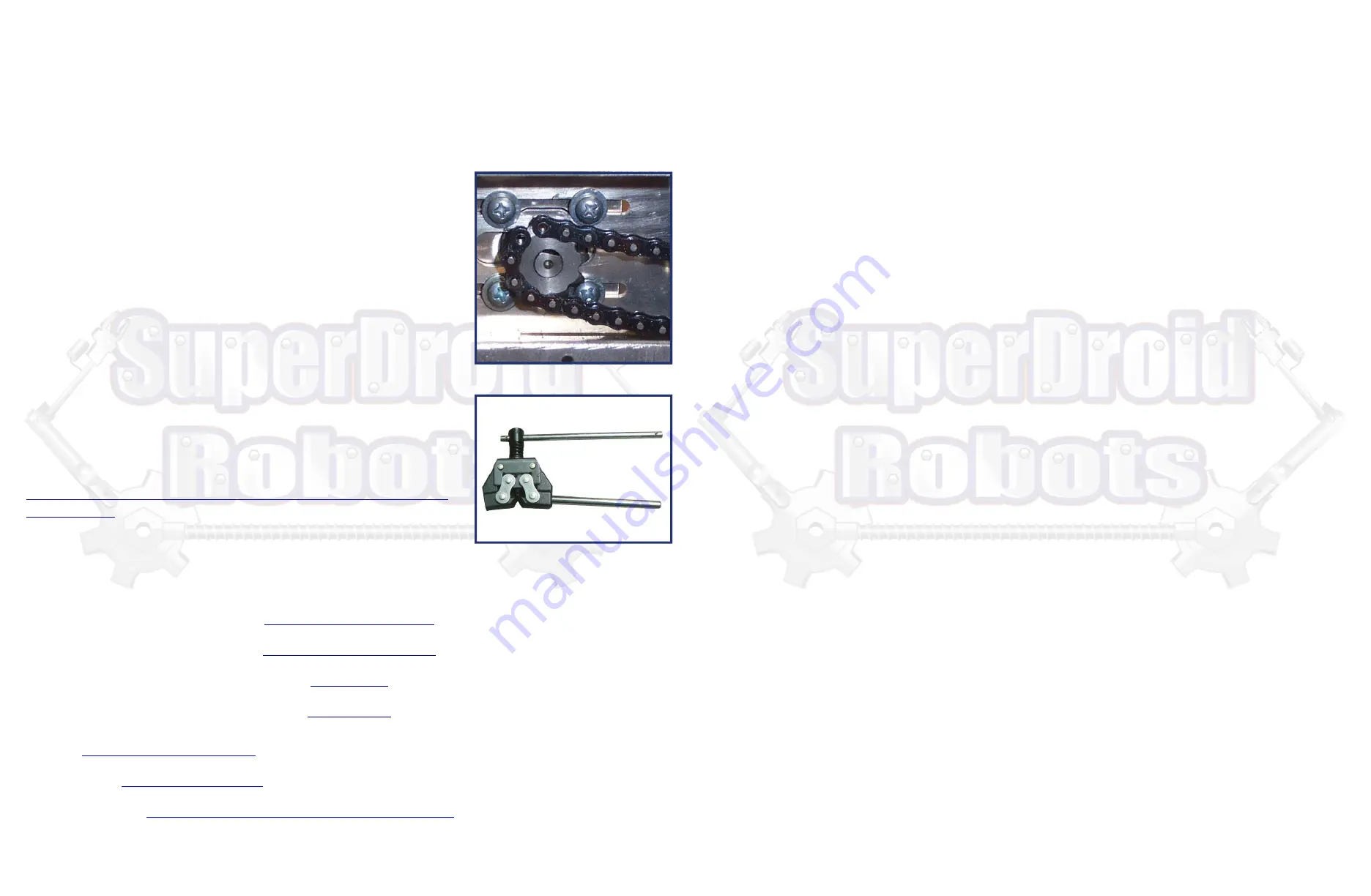
1. Adjust the motor to it’s approximate middle position, then measure out the required length of chain. You will want
full links as shown in the Fig 3.1 below to insert the master link through. You will be removing the outer cross-links.
2. We recommend using a chain breaker tool (Fig 3.2)
Fig. 3.1 Link positioning
Fig. 3.2 Chain Breaker
https://www.superdroidrobots.com/shop/custom.aspx/electrical-
schematics/97/
Electric Motor Hookup Support
Electric Power Hookup Support
Soldering Tips
Crimping Wires
1.
Before powering on the robot make sure it is up on blocks so the wheels can spin freely. Occasionally some or
all of the wheels start as soon as the motor controller gets power. In this case the settings of the motor controller need
to be changed.
2.
Make sure to use the correct DIP switch settings. If using a Sabertooth motor controller in R/C mode switch 1
should be DOWN (closest to the number) and all other switches should be UP. If using a different mode see the manual
for the motor controller you are using on Dimension Engineering’s website.
5. Operation
Binding a Spektrum Remote
1.
Insert the bind plug into the receiver and power on the robot.
2.
While pressing the Bind button, power on the transmitter.
3.
Release the Bind button after the receiver’s LED stays illuminated. This indicates the receiver is bound to the
transmitter.
4.
While the robot and transmitter are still powered on, remove the bind plug from the receiver. The transmitter is
now bound to the receiver and will connect automatically the next time both are powered on. Do not try to drive the
robot before the transmitter connects to the receiver. Keep the drive joystick in the center position until it connects.
The joystick is calibrated once a connection is made and will remember the position of the joystick as the center
position. This will cause the robot to move erratically.
5.
If the wheel aren’t moving as desired, it may be necessary to swap the Alieron and Elevator plugs or to reverse
the channels on the transmitter. To reverse channels see the instructions for “Servo Reversing” in the Spektrum
documentation.
6. Common Problems & Solutions
Note: The smooth and successful operation of this robotic system requires a lot of time and training. Take care of your new
robot, so that it will take care of you. Treat it the same way you treat any other important piece of equipment. This system is
NOT INDESTRUCTIBLE
A. Robot is unresponsive
First try turning everything off and waiting 30 seconds before turning it back on again. Components may have been
left on, or not fully charged. Leave the system to charge for one to two hours. Try operating the robot. If there are still
issues with batteries not taking a charge, one or more batteries is dead, and will have to be replaced.
B. Broken or Missing Parts
In the event there are any broken or missing parts stop using the robot. Inspect the components to determine if the
robot absolutely requires these parts to function. Some parts can be broken, and the robot will still function in order to
complete a mission. Other parts are critical to the function of the robot and require repair or replacement. If it is
unknown as to whether the robot will function properly, stop using the robot and contact SuperDroid Robots Inc. by
telephone or e-mail.
A. Videos
http://youtube.com/SDRRobots
B. Blog & Forum
http://www.sdrobots.com
C. Customer Support
http://www.superdroidrobots.com/shop/contactus.aspx
General Support


