5
SECTION 2 - OPERATION
Camera and Movement Controls
Video Mode & Photo Mode
NOTE
Practice operating the robot in front of you to understand how the movement controls work.
This will help when operating the robot out of view using the camera.
LEFT JOYSTICK -
This joystick controls the camera tilt system.
Pushing forward or back on the joystick causes the camera to tilt
up or down.
RIGHT JOYSTICK -
This joystick controls the movement of the
GPK-32. Push forward or back to move the robot in those
directions. Pushing the joystick left or right rotates the GPK-32 in
place.
LEFT
RIGHT
Figure 2A
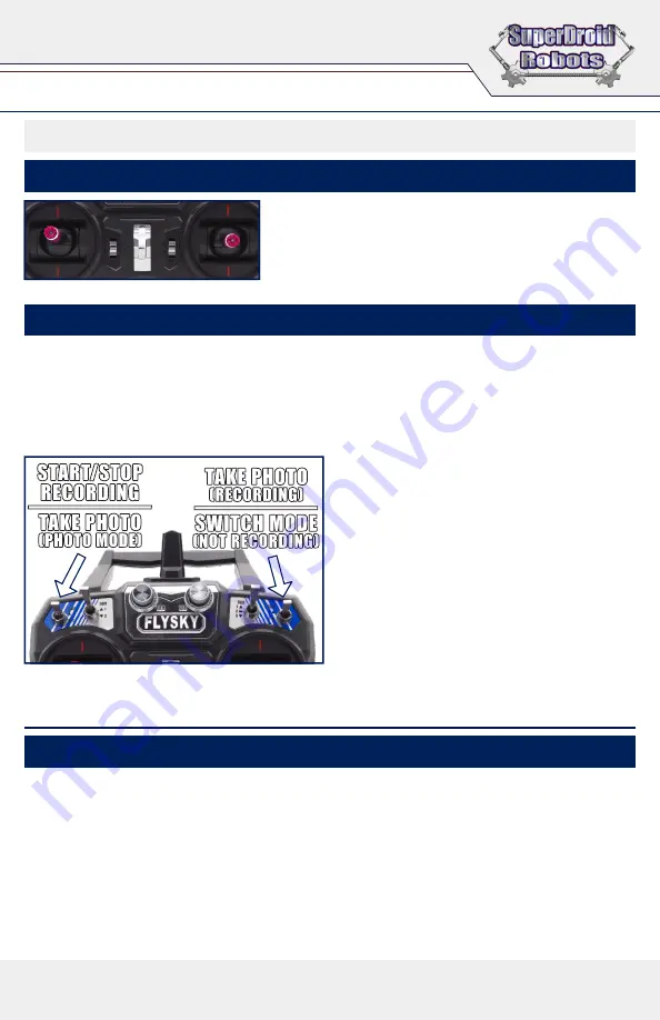
START/STOP
RECORDING
TAKE PHOTO
(PHOTO MODE)
TAKE PHOTO
(RECORDING)
SWITCH MODE
(NOT RECORDING)
SECTION 3 - CHARGING
Charging the Robot & Monitor
TO CHARGE THE ROBOT’S BATTERIES
• Follow the DeWalt instructions to charge the removable 20v battery packs.
TO CHARGE THE MONITOR
• Before charging the video monitor, make sure it is powered off using the power switch on the back.
• Plug the provided charger into a 120v outlet and insert the barrel plug into the charging port on the back
of the monitor, next to the power switch.
• The light on the monitor will turn red while it is charging. Once the light is no longer red, the monitor is
done charging.
THE REMOTE CONTROLLER IS POWERED BY AA BATTERIES.
The camera is controlled by the two outer most switches at the top of the controller. They are the two shorter
switches and will be referred to as the
LEFT
and
RIGHT
switch. Each time one of those two switches is
flipped, either up or down, an action will be performed.
If an SD card with free space is in the camera when the robot is turned on, the camera will automatically start
recording. A red circle will appear in the upper right of the monitor, along with a red timer to show how long
you have been recording. To
take a picture while recording
,
flip
the
right
switch once. “
Capture Done
” will
flash on the screen to indicate a picture was taken. Wait about 5 seconds between each picture.
To
STOP
the recording
flip
the
left
switch once. The
red circle will go away, and the numbers will change to
white and display how much recording time is left on
the SD card. In video mode the left switch will always
start or stop the recording.
The right switch changes functions when the camera
isn’t recording. When flipped it will change the camera
between
Photo Mode
and
Recording Mode
.
Recording mode will show “
1080/60
” at the top of the
monitor and Photo mode will show “
4M
”.
To take a photo in photo mode,
flip
the
left
switch.
The screen will flash black to indicate a photo was
taken. In Photo mode, you only need to wait about 2
seconds between pictures. Use Photo mode for still
pictures with no video recording.
Summary of Contents for GPK-32
Page 7: ...7 ADDITIONAL NOTES ...


