background image

Superabrasive   

User Manual   Original Language 

Lavina® 30GEB   

1/2021 

26 


Figure 8.4.5 

Figure 8.4.6 

Figure 8.4.7 

Figure 8.4.8 

Figure 8.4.1 

Figure 8.4.2 

Figure 8.4.3 

Figure 8.4.4 

Figure 8.4.9 

Figure 8.4.10 

Figure 8.4.11 

Figure 8.4.12 

Summary of Contents for LAVINA ELITE L30GEB

Page 1: ...Superabrasive User Manual Original Language Lavina 30GEB 1 2021 1 LAVINA ELITE L30GEB User Manual Tech Support Line 800 987 8403 www superabrasive com info superabrasive us...

Page 2: ...Superabrasive User Manual Original Language Lavina 30GEB 1 2021 2...

Page 3: ...arts are not warranted Superabrasive is not liable for defects arising out of use of non OEM parts The Warranty is void if the purchaser has not followed the maintenance plan stipulated by the machine...

Page 4: ...LS 18 VACUUM CONNECTION 18 USE HORIZONTAL PROPANE TANK 18 CONTROL BOARD 19 THE CONTROL BOARD 19 STARTING THE MACHINE 19 OPERATING THE MACHINE 19 STOPPING THE MACHINE 19 5 TOOLS AND ACCESSORIES 20 TOOL...

Page 5: ...NSTALLATION 43 12 10 ENGINE BASE PARTS 44 12 11 GUARD ASSEMBLY 44 12 12 TOP COVER 45 12 13 TOP COVER ASSEMBLY 45 12 14 BOTTOM COVER 1 PARTS 46 12 15 PLANETARY DRIVE PARTS 47 12 16 PULLEY UNIT ASSEMBLY...

Page 6: ...frame is adjustable in height and allows the operator to work in a correct and safe posture The LED lights Fig 1 1 Fig 1 2 enables the operator to work in darker areas Existing lighting system does n...

Page 7: ...number needed for maintenance purposes CUSTOMER SERVICE For customer assistance and technical support call your local distributor or call Superabrasive Inc at 1 800 987 8403 or visit us at www superab...

Page 8: ...risks Such risks are Position Risks due to operator s incorrect working position Entanglement Risks due to wearing inappropriate working clothes Training Risks due to lack of operational training PRO...

Page 9: ...mental Solutions suggests usage when occupancy of a given work area is minimal CARB EPA The California Air Resource Board CARB and Environmental Protection Agency EPA also set limits for propane power...

Page 10: ...l Drager SENSIDYNE gas sampling system with YB 11038 Sensidyne dectector tubes DRAGER gas sampling system with YB 4620 Drager detective tubes GAS TECH Model CO 95 ENERAC POCKET 60 Manufactured by Ener...

Page 11: ...ane cylinders always should be stored outside in an upright position in a secure tamperproof steel mesh storage cabinet This cabinet may be located next to the building but with at least five feet 1 5...

Page 12: ...work in a correct and safe posture Fig 3 1 Fig 3 2 Fig 3 3 Fig 3 5 Choose the upright position to move easy the machine The machine has two built in weights Each one could stay in upward Fig 3 5 or d...

Page 13: ...only when you wish to move the machine LIFTING Lifting the machine by crane is possible by using the handles of the carriage see fig 3 13 Do not lift any other loads on the machine Always use hoistin...

Page 14: ...s of operating conditions SYSTEM COMPONENTS The following parts are included with the system Electronics Module Integrated Wire Harness Fuel Control Valve Fuel Control Housing O2 Sensor LPG Regulator...

Page 15: ...r will then prompt you to reset that interval SLEEP MODE To conserve equipment battery life theFuel Minder will enter sleep mode if there are no key inputs or engine activity The backlight will dim af...

Page 16: ...ECT to move to the Day field Again use the and buttons to select the desired day Once you have the desired date hold SELECT for 2 seconds and a prompt to save the information will appear Engine Info T...

Page 17: ...nal valve Figure 4 3 so the water could flow from the tank through the internal valve over the tools You can adjust the water flow by putting the internal valve in an intermediate position external wa...

Page 18: ...Cam Lock inlet C250 vacuum hose diam 2 5 in 63mm Fig 4 9 Position 2 USE HORIZONTAL PROPANE TANK The standard Lavina 30GEB is equipped with vertical propane tank with vapor draw If necessary the machi...

Page 19: ...maintenance will insure easy starting Engage starter 4 for a MAXIMUM of 5 to 6 seconds or until the engine fires Serious starter damage will result if this is exceeded and the warranty may not apply O...

Page 20: ...ting mounting and dismounting of the foam plates Always use the key for mounting Item number is A03 00 00 00 SECURITY PLATE FOR QUICKCHANGE PADS Plate Fig 5 2 used to secure the Quickchange tools Item...

Page 21: ...pads are produced in four different bonds for super hard hard medium and soft concrete in a variety of grit sizes They are offered with 1 or 2 buttons or rectangular segments which allows you to custo...

Page 22: ...ne the operator should conduct a visual inspection of the machine Any defect should be solved immediately Pay attention to power cords plugs and vacuum hoses loose bolt or screws Tool holders Buffers...

Page 23: ...n See TROUBLESHOOTING Dismount the tool holders See Troubleshooting replace all parts elastic element buffers sealers with the slightest damage or consume Return machine to authorized service center f...

Page 24: ...the engine will run normally If it does not call your customer service Starter barely turns the engine over or the solenoid just clicks The battery is likely low in charge This can be remedied by rec...

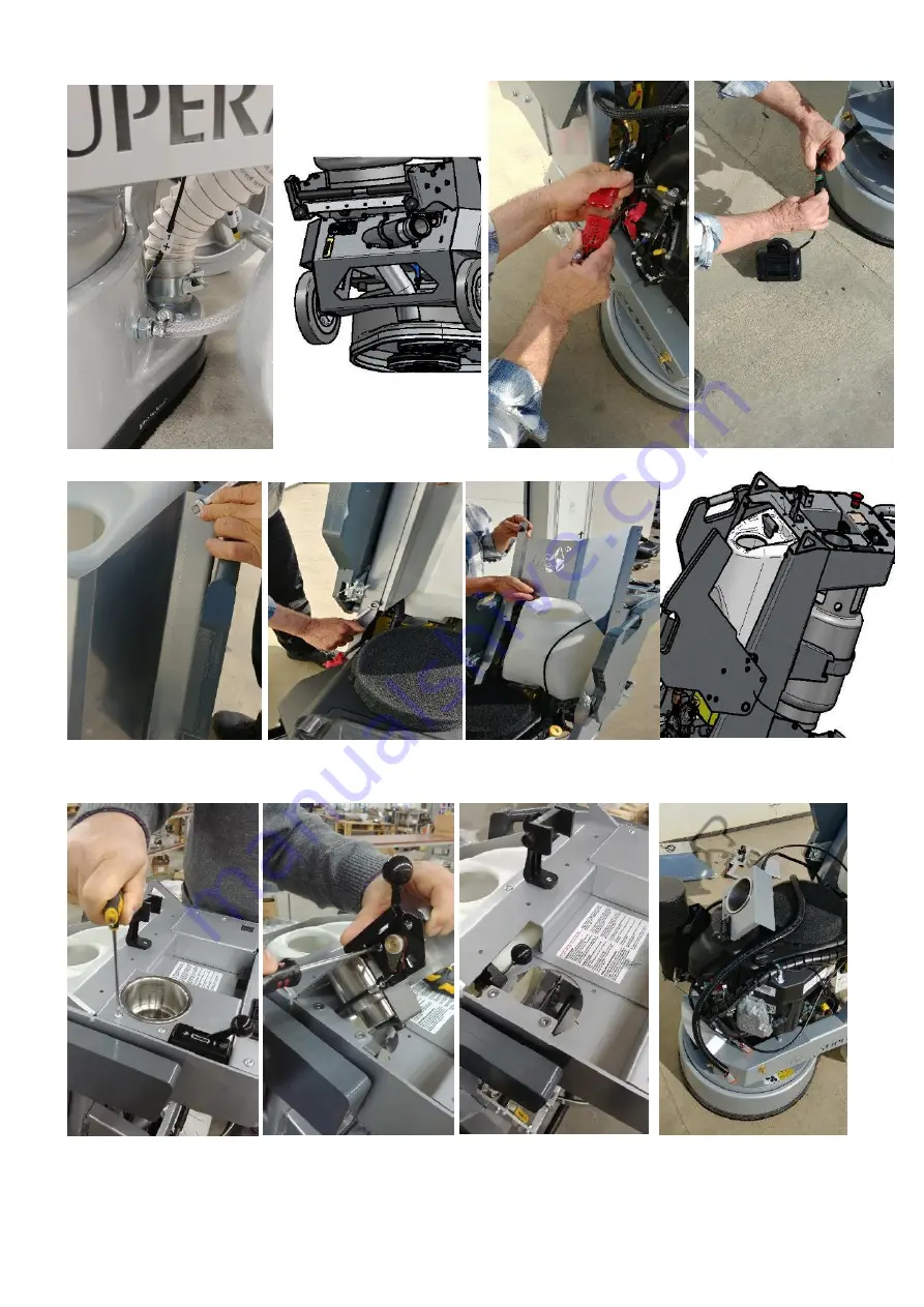
Page 25: ...aintained at the FULL level 8 3 DISMOUNTING MOUNTING THE GUARD You can dismount and mount the safe guard without separating the carriage from the main head Put the machine in position to change the to...

Page 26: ...User Manual Original Language Lavina 30GEB 1 2021 26 Figure 8 4 5 Figure 8 4 6 Figure 8 4 7 Figure 8 4 8 Figure 8 4 1 Figure 8 4 2 Figure 8 4 3 Figure 8 4 4 Figure 8 4 9 Figure 8 4 10 Figure 8 4 11 F...

Page 27: ...sconnect the control module from the motor Disconnect the coupling disconnect the cable and move it to the main head Fig 8 4 13 Fig 8 4 14 Fig 8 4 15 Fig 8 4 16 Fig 8 4 17 Fig 8 4 18 Fig 8 4 19 Figure...

Page 28: ...belt protection Fig 8 5 2 Loose the motor base plate Fig 8 5 3 release the tension device Fig 8 5 4 and take out the belt Fig 8 5 5 Take off the engine Fig 8 5 6 Reassemble in the same manner Fig 8 5...

Page 29: ...7 1 and remove the holder Fig 8 7 2 When the tool holder is dismounted you can change the sealers V Ring and Felt Ring By loosening four Hex cap flange bolts Fig 8 7 3 the adaptor comes loose Unscrew...

Page 30: ...8 8 12 are reliably tighten Mount the holder on the machine using the same socket as mentioned in 8 6 Fig 8 8 10 Fig 8 8 11 The retaining washer fits into the central hole C of adaptor and the four bo...

Page 31: ...n is replaced with new one when the step drive of the chain tensioner is finished or there is a break in the integrity of the chain Unscrew the bolts Fig 8 9 1 and take out the cover Lift the machine...

Page 32: ...Fig 8 8 6 and the screw Fig 8 8 5 ATTENTION NEVER OVER TENSION THE CHAIN THE CHAIN WILL BE DAMAGED 8 11 REPLACING THE PLANETARY DRIVING CHAIN WHEEL AND PLANETARY TENSIONER Check and repeat the instru...

Page 33: ...e is NOT permissible at any time as this can damage the high quality low stretch tension cord and other components This damage is often not visible Arrange the belts in pos 6 as per the scheme paying...

Page 34: ...ad free Fig 8 11 14 Fig 8 11 15 Insert the screws up to revolution and by alternating until the conical sleeve pull up the belt pulley The conical sleeve must be aligned in height with the belt washer...

Page 35: ...need magnetic deep metric socket 10mm with outside diameter not more than 11 16 in to unscrew the six bolts Fig 8 12 3 Fig 8 12 4 Fig 8 12 5 Driven Chain Wheel is composed by two symmetrical halfs Fi...

Page 36: ...able or needs to be replaced send the machine back to Superabrasive or a local distributor where a professional disposal complying with the environment laws and directives is guaranteed 10 MANUFACTURE...

Page 37: ...erabrasive Inc cannot deny warranty solely for the lack of receipts or for your failure to ensure the performance of all scheduled maintenance As the SORE owner you should however be aware that Supera...

Page 38: ...ted part provided that such diagnostic work is performed at a warranty station 7 Superabrasive Inc is liable for damages to other engine or equipment components proximately caused by a failure under w...

Page 39: ...d 1 5 2 L20GX 20 00 13 Cover 1 5 3 30301230243 Screw M6x16ISO7380F 10 9 4 5 4 L20GX 40 20 00 Control Board With throttle cable 1 5 5 L20E20 10 00 Top Bracket 1 5 6 A78 00 00 00 Tank Assembly 1 5 7 303...

Page 40: ...30313000173 Charger 1 7 30301240143 Distance Bush 2 8 GT EM40 Complete Monitor Assembly 1 9 30301221001 Washer 4DIN125A 2 10 30301240114 Nut M4DIN985 2 11 30311000753 Fuse Holder 1 12 30313000253 Fuse...

Page 41: ...Superabrasive User Manual Original Language Lavina 30GEB 1 2021 41 12 5 CARRIAGE Figure 12 5...

Page 42: ...HGP270 Phone clip mount 1 35 UT BS0201 LED Light 1 13 L13GX21 10 00 Handle Assembly 1 36 30301240106 Nut 8DIN985 8 14 L20GX 23 00 01 End Cover 2 37 88 00 00 Water Valve assembly 1 15 30301210051 Bolt...

Page 43: ...0316000013 Quick change nozzle 1 12 8 LAVINA 30GEB WATER TANK Item No A78 00 00 00 No Item No Description Pcs 1 A33 00 02 K Water Tank K 1 2 30316000001 Filter 1 3 30316000015 Nipple 1 12 9 LAVINA 30G...

Page 44: ...30301230004 Screw M8X25DIN912 2 12 30308000145 Endless Transmission Belt 1 13 L30GEB10 70 00 Guard Assembly 1 14 30301210004 Bolt M8X40DIN933 1 15 30301221004 Washer M8DIN125A 1 16 30301210051 Bolt M6...

Page 45: ...IN6921 4 6 30302000049 V Ring Type A 1 7 L25GEB19 00 00 Top Cover Assembly 1 8 30301210048 Bolt M6X12DIN6921 3 9 30301210051 Bolt M6X16DIN6921 6 10 L25GE19 20 00 2 Inspection Cover 1 11 L25GE10 00 99...

Page 46: ...2000005 V Ring Type A 3 5 30301210051 Bolt 6 16DIN6921 15 6 L25X 14 00 00 R2 Bottom Cover Assembly 1 6 1 L25X 14 00 01 Bottom Cover 1 6 2 30301230017 Screw M6X10DIN7991 10 9 36 6 3 L25LS 14 00 03 Oute...

Page 47: ...it Assembly 3 13 1 30301210032 Bolt M8X35DIN6921 4 14 L25E10 00 01 K Disc 1 15 30302000008 V Ring Type A 1 16 30301250007 Retaining Ring 1 17 08BH 1 78 Chain 1 18 30303000024 Roller Assembly 2 19 3030...

Page 48: ...nce Ring 1 5 L25X 04 00 00 Pulley Unit Assembly 1 6 L25X 10 00 44 Front Washer 1 7 30301230009 Screw M5X12DIN912 1 12 17 LAVINA 30GEB BOTTOM COVER 2 PARTS No Item No Description Pcs 1 30308000152 Timi...

Page 49: ...0301230161 Screw M8X12DIN7991 10 9 12 2 2 A25 00 10 Buffer 6 3 A41 20 03 K Driving Set A41 1 3 1 A41 20 03 Elastic Element 1 3 2 30301240124 Self Locking Nut M6DIN980V 12 3 3 30301230123 Screw M6X30DI...

Page 50: ...escription Pcs 1 L25GE02 10 00 K Lever mount 1 2 L25GE02 20 00 K Lever Assembly 1 3 L30GE02 00 00 Third Wheel Set 1 3 1 L30GE02 10 00 Third Wheel Assembly 1 3 2 L30GE02 00 01 Key Left 1 3 3 L30GE02 00...

Page 51: ...S FOR THE THIRD WHEEL 1 Remove the Bumper part L30GEB L30GEB01 00 00 from the machine 2 Remove part A and install part B in its place 3 Mount the part C Lever mount and part D Key on the brackets 4 Re...

Page 52: ...Superabrasive User Manual Original Language Lavina 30GEB 1 2021 52 12 22 ELECTRICAL SCHEMES WITH KAWASAKI ENGINE Figure 12 22...

Reviews: