Chapter 2: Installation
2-13
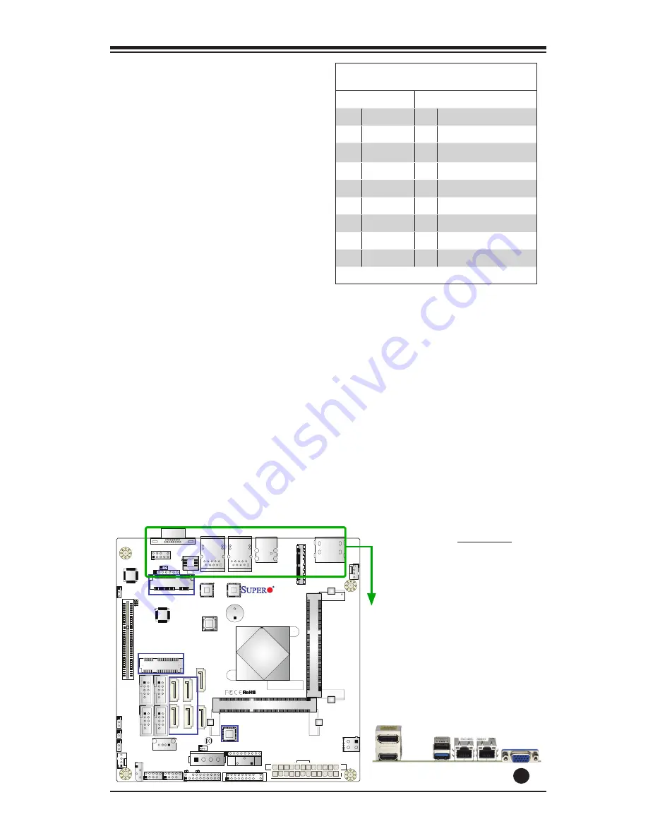
A. VGA Port
A
X10SBA(-L)
Rev.1.01A
JSMB
1
J31
JBT1
BT2
M-SA
TA
0
M-SA
TA
1
M-SA
TA
2
M-SA
TA
3
JP1
LAN1
LAN2
JDIMM2
PJ1
JF
1
JTPM1
JOH
1
JSPDIF_OUT
JPUSB1
JP
AC
1
JPME
2
JD1
VGA
FAN1
FA
N2
I-S
AT
A1
COM4 COM2
SP1
JSD1
JDIMM1
LED3
LED4
LED2
JPW1
SMBUS1
SLOT1 PCI-E 2.0 X2 (IN X8
)
USB4/5
USB6
AUDIO FP
SODIMM2 (1.35V only)
USB1(2.0)
USB0(3.0)
CPU
(Install first)
SODIMM1(1.35V only)
eDP
Non-ECC DDR3 Require
d
HDMI/DP
COM3
FP CTRL
BIOS
BAR CODE
J1
(for mini-PCI-E only)
(for M-SATA only)
J2
COM1
(for X10SBA only)
(for X10SBA only
)
(for X10SBA only)
(for X10SBA)
LED1
LED5
USB2/3
I-SA
TA
0
Video Connector
A Video (VGA) connector is located
next to the LAN2 Port on the I/O
backpanel. This connector is used
to provide video display. Refer to the
board layout below for the location.
VGA Pin
Definitions
Pin# Definition Pin# Definition
1
Red
10
Ground
2
Green
11
MS0
3
Blue
12
MS1: SDA (DDC Data)
4
MS2
13
HSYNC
5
Ground
14
VSYSNC
6
Ground
15
MS3: SCL (DDC CLK)
7
Ground
16
Case
8
Ground
17
Case
9
NC
NC= No Connection
Summary of Contents for X10SBA
Page 1: ...X10SBA X10SBA L USER S MANUAL Revision 1 0a ...
Page 22: ...1 14 X10SBA X10SBA L User s Manual Notes ...
Page 54: ...2 32 X10SBA X10SBA L User s Manual Notes ...
Page 81: ...Chapter 4 AMI BIOS 4 21 Link Status MAC Address Virtual MAC Address ...


