


(HML
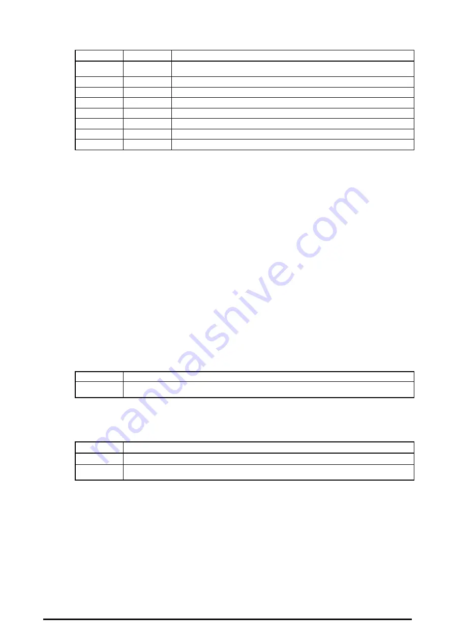
1) 0: Flag
It indicates the operation condition of the S-LINK system.
bit R/W
Assignment
7 R/W
Confirmation of communication frame completion
(Output data communication completed with ‘0’ after writing in ‘1’)
6 R/W
System set (1: Read condition of S-LINK I/O unit connection)
5
㧙
Unusable (=0)
4 R
Condition of S-LINK communication (1: Communicating)
3
R
Error 4 (1: Wire disconnection or abnormal I/O unit)
2
R
Error 3 (1: Abnormal voltage level between D and G)
1
㧙
Unusable (=0)
0
R
Error 1 (1: Short-circuit between D and G)
( ‘R/W’
ψ
Read out/ Write in, ‘R’
ψ
Read out)
bit 0, 2, 3 : ‘Error 1’, ‘Error 3’ and ‘Error 4’ are ‘1’ when the respective error occurs.
bit 4
: It is ‘1’ when communicating with the S-LINK I/O units.
bit 6
: It has the same operation as ‘4. FUNCTIONAL DESCRIPTION
System set but-
ton’. When ‘1’ is written, the connection condition of the S-LINK I/O units at that time
is read.
(It automatically returns to ‘0’ after the reading.)
bit 7
: In case of sending different outputs to the same address, the former output data will
be ignored if the next output data is written in before the former output data has been
transmitted to the S-LINK output unit.
‘Confirmation of communication frame completion’ is used to confirm whether the out-
put data has been transmitted to the S-LINK output unit.
When number ‘1’ is written after writing in output data, it automatically returns to ‘0’
after transmitting the output data to the S-LINK output unit. So, transmission error of
output data will be prevented if you write in the next output data after its returning to
‘0’ is confirmed by the program.
Notes: 1) Error 1 and Error 3 are held on until fault rectification.
2) Error 4 is held on. It can be released (‘0’) by switching on again either the S-LINK system side power
supply (
㧗
24V DC) or the Compact PCI bus power supply (computer power supply) after fault rectification.
(HML
1) 1: Number of connected S-LINK I/O units / First address of units where Error 4 occurs
Under normal condition: It indicates the number of connected S-LINK I/O units.
bit Assignment
7 to 0
Normal: Number of connected S-LINK I/O units 0 to 128
(In hexadecimal number system, 00H to 80H)
Note: When the same address is set for several S-LINK I/O units, they are regarded as one unit.
Under Error 4 condition: It indicates the first addresses of S-LINK I/O units where Error 4 has occurred.
In case Error 4 occurs at several addresses, bit 7 = ‘1’.
bit Assignment
7
1: Error 4 occurs at several I/O units (in case the number of units with Error 4 = 1, bit = ‘0’)
6 to 0
Under Error 4 condition: First addresses of S-LINK I/O units with Error 4 (0 to 127)
(In hexadecimal number system: 00H to 7FH)
Note: ‘First address of units with Error 4’ is held on. Error 4 can be released (‘0’) by switching on again either the
S-LINK side power supply (
㧗
24V DC) or the Compact PCI bus power supply (computer power supply) after
fault rectification.
8