Suntor ST11HPT User Manual Download Page 9

9th

performance. For example, for a link (8MHz channel) with a signal strength of at least –75dBm, a TX rate of 16-QAM 3/4
FEC is recommended. Setting to the highest rate with a poor link may result in reduced performance.

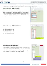
3.2. Channel Bandwidth

Default

4Mhz

:

Select the channel bandwidth from the list. Refer to the specifications to see
the relationship and performance between channel band, width,throughput
and sensitivity.Generally a larger channel has greater throughput, at the cost of
sensitivity, while a smaller channel tends to be more robust, but at the cost of
throughput.

3.3. Channel-Frequency

Default

2479Mhz

:

2402 - 2482 (1MHz BW, CH 1-81)
2402 - 2482 (2MHz BW, CH 1-81)
2405 - 2479 (4MHz BW, CH 4-78)
2407 - 2477 (8MHz BW, CH 6-76)

3.4. Wireless Distance

Default

10km

:

The Wireless Distance parameter allows a user to set the expected distance the
wireless signal needs to travel. The TDD-COFDM sets various internal timeouts to
account for this travel time. Longer distances will require a higher setting, and
shorter distances may perform better if the setting is reduced.

Summary of Contents for ST11HPT

Page 1: ...dd cofdm equipment 8th 2 Restart TDD COFDM Control Panel software 8th 3 RF Configuration method 8th 3 1 TX Rate 8th 3 2 Channel Bandwidth 9th 3 3 Channel Frequency 9th 3 4 Wireless Distance 9th 3 5 RX...

Page 2: ...nal injury or damage to properties to some extent Pay attention to operation safety II Precautions for integration 1 Be sure to use the parts provided by SUNTOR 2 Please not reverse connect power line...

Page 3: ...the PTZ camera and HDMIRX video communication board will be greatly improved 8 The HDMI cable and antenna may cause interference to GPS They should be kept far away from the GPS module and its cables...

Page 4: ...en Powering On 1 Before using make sure that all cables are secure and reliably and all components can work properly 2 After starting the product check it for proper operation by observing whether the...

Page 5: ...nd terminal can improve the signal or image effect 7 The camera should be fully charged to ensure normal video output 8 ST5 11 30HPT has the functions of two way communication of image data and serial...

Page 6: ...w seconds the starting is complete Light 1 Green 2 Green 3 Green 6 blue 4 Red are normally on Light 5 will fast blink 4 When data transmission goes well WL green light will flicker Remark Light1 2 3 a...

Page 7: ...ion location is the UAV ground bracket With the antenna inside the bracket can only use fiberglass material 4 If the ground bracket is automatically retracted the antenna can be installed in the lower...

Page 8: ...r the IP address Next click Connect TDD button 2 Restart TDD COFDM Control Panel software click Restart TDD button 3 RF Configuration method 3 1 TX Rate Default QPSK FEC 1 2 This setting determines th...

Page 9: ...a larger channel has greater throughput at the cost of sensitivity while a smaller channel tends to be more robust but at the cost of throughput 3 3 Channel Frequency Default 2479Mhz 2402 2482 1MHz B...

Page 10: ...d to the antenna connector of the TDD_COFDM Unless required the Tx Power should be set not for maximum but rather for the minimum value required to maintain an adequate system fade margin 4 Seria Conf...

Page 11: ...TCP server The TCP session is terminated by this same unit when the data exchange session is completed and the connection timeout has expired If a TCP connection cannot be established the serial port...

Page 12: ...s you should correct another device s Remote IP Addr into the same IP SET or the serial port will lose connection For example you have changed the master s IP address to 192 168 55 5 the you should co...

Reviews: