Suntor ST11HPT User Manual Download Page 5

5th

3. Check the surrounding environment for to ensure there is no other 2.4GHz devices to cause

interference. If use the Futaba remote controller, the controller should be adjusted into the French
mode. Otherwise, the video transmission performance of ST5/11/30HPT may be serious affected and
also the Futaba transceiver may be in the abnormal status and accidents may be caused.

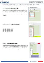
4. Remark: How to adjust the Futaba controller into French mode:

[LINKAGE MENU]→FRQUENCY→ RTN b→ [AREA]→[FRANCE]

5. Before use, check the electric quantity of the ground terminal. If the ground terminal is OFF, the

built-in radio receiver of the onboard terminal will be out-of-control.

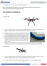
6. Pay attention to the angle and direction of the antenna of the ground terminal during flight. In case of

poor signal or image quality, adjusting the inclination of the antenna of the ground terminal can
improve the signal or image effect.

7. The camera should be fully charged to ensure normal video output.

8. ST5/11/30HPT has the functions of two-way communication of image data and serial port data. If the

transmitted ground image is stuck or stopped for more than 10s but less than 30s, it means that the
radio channel signal is weakened or the radio channel is narrowed. In this case, the aircraft must not fly
farther away from the ground. In order to ensure the normal communication of serial data and the
safety of the aircraft, the distance between the aircraft and ground terminal should be immediately
shortened. Otherwise, the built-in radio receiver of the onboard terminal will be out-of-control.

9.

8. If required, purchase electronic devices (such as HD displays, Network cables, etc.) with good
electromagnetic shielding effects.

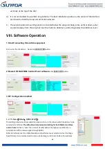
VI. Operating Instructions & Steps

1. Make TX and RX and accessories ready.

Besides the whole equipment we supply, you need to
also make sure the video source, display and power
ready before operating.

Summary of Contents for ST11HPT

Page 1: ...dd cofdm equipment 8th 2 Restart TDD COFDM Control Panel software 8th 3 RF Configuration method 8th 3 1 TX Rate 8th 3 2 Channel Bandwidth 9th 3 3 Channel Frequency 9th 3 4 Wireless Distance 9th 3 5 RX...

Page 2: ...nal injury or damage to properties to some extent Pay attention to operation safety II Precautions for integration 1 Be sure to use the parts provided by SUNTOR 2 Please not reverse connect power line...

Page 3: ...the PTZ camera and HDMIRX video communication board will be greatly improved 8 The HDMI cable and antenna may cause interference to GPS They should be kept far away from the GPS module and its cables...

Page 4: ...en Powering On 1 Before using make sure that all cables are secure and reliably and all components can work properly 2 After starting the product check it for proper operation by observing whether the...

Page 5: ...nd terminal can improve the signal or image effect 7 The camera should be fully charged to ensure normal video output 8 ST5 11 30HPT has the functions of two way communication of image data and serial...

Page 6: ...w seconds the starting is complete Light 1 Green 2 Green 3 Green 6 blue 4 Red are normally on Light 5 will fast blink 4 When data transmission goes well WL green light will flicker Remark Light1 2 3 a...

Page 7: ...ion location is the UAV ground bracket With the antenna inside the bracket can only use fiberglass material 4 If the ground bracket is automatically retracted the antenna can be installed in the lower...

Page 8: ...r the IP address Next click Connect TDD button 2 Restart TDD COFDM Control Panel software click Restart TDD button 3 RF Configuration method 3 1 TX Rate Default QPSK FEC 1 2 This setting determines th...

Page 9: ...a larger channel has greater throughput at the cost of sensitivity while a smaller channel tends to be more robust but at the cost of throughput 3 3 Channel Frequency Default 2479Mhz 2402 2482 1MHz B...

Page 10: ...d to the antenna connector of the TDD_COFDM Unless required the Tx Power should be set not for maximum but rather for the minimum value required to maintain an adequate system fade margin 4 Seria Conf...

Page 11: ...TCP server The TCP session is terminated by this same unit when the data exchange session is completed and the connection timeout has expired If a TCP connection cannot be established the serial port...

Page 12: ...s you should correct another device s Remote IP Addr into the same IP SET or the serial port will lose connection For example you have changed the master s IP address to 192 168 55 5 the you should co...

Reviews: