background image

5

6

2

Safety rules

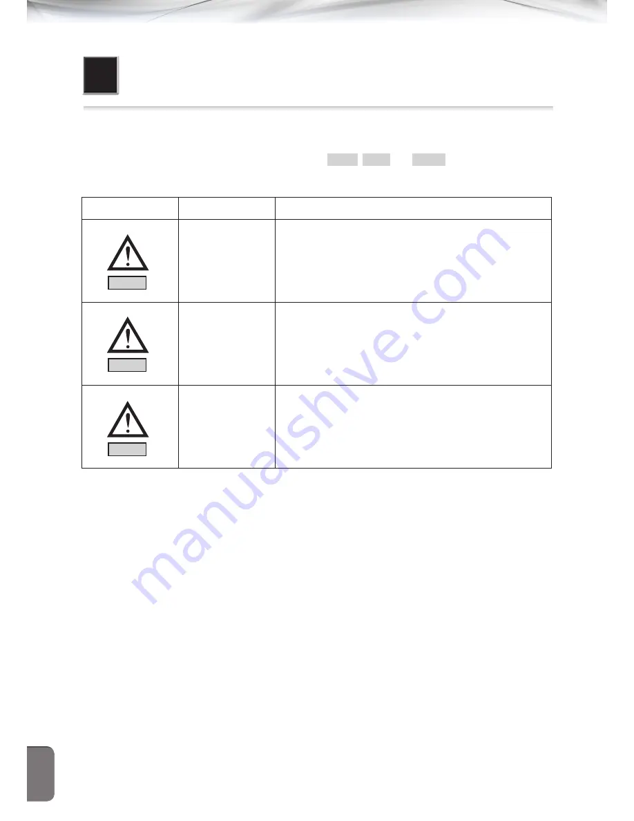
2.1 Description of safety indicators


 This guidebook contains such safety indications as caution, danger, and warning. If the instructions are not 
observed, it may bring about physical injuries or physical damages or mechanical damages. 

No.

Name

Contents

CAUTION

If a user handled with the machine wrongly, it is expected that 
physical injury or physical damage may occur.

WARNING

If a user handled with the machine wrongly, it is expected that 
a user may be deceased or be in a critical injury.

DANGER

If a user handled with the machine wrongly, it is expected that 
a user may be deceased or be in a critical injury and that is in 
top emergency situation.


WARNING

WARNING

WARNING

Summary of Contents for SPS/F-1811 Series

Page 1: ...MME 121213 사용설명서 15두형 자동자수기 SPS F 2211 Series SPS F 1811 Series SPS N 2211 Series Electronically Controlled Pattern Sewing Machine USER S MANUAL USER S MANUAL SunStar CO LTD ...

Page 2: ......
Page 3: ...uct please read this guide carefully to have the machine perform properly and thoroughly 3 For a better performance of product the specification is subject to change without notices in advance 4 This product is designed manufactured and sold for a sewing machine for industrial use Please do not use this product for other uses 5 A grade equipment Broadcasting and telecommunication equipment for bus...

Page 4: ...4 6 Attachment of the safety plate 13 4 7 How to control the speed of increasing and decreasing of the upper feed plate 14 4 8 How to stand the sewing machine 14 4 9 How to inject compressed air and adjust the air pressure 15 4 9 1 Connection of the compressed air 15 4 9 2 How to adjust the air pressure 15 5 Preparations before using the machine 16 5 1 How to lubricate 16 5 2 Needle 17 5 3 Thread ...

Page 5: ...efault of Y shaft 35 6 13 Control of the parts related to thread trimming 35 6 13 1 Setting of the thread trimming cam 35 6 13 2 How to adjust the link stopper screw 36 6 13 3 Setting of the thread trimming shaft position 36 6 13 4 Setting of the link stopper position 36 6 13 5 Setting of the thread trimming solenoid position 37 6 13 6 Fix of the moving mes and the fixed mes 38 6 14 How to mount a...

Page 6: ...plate 20 Pneumatic Monolithic Feeding Frame 21 Pneumatic Separately Driven Feeding Frame with Two Step Stroke Device 22 Pneumatic Separately Driven Feeding Frame 23 Pneumatic Separately Driven Feeding Frame with Inverting Clamp Device Division of feed frame Division of stitch specification Division of pattern model F Full Closed Pulse Motor N New Network System Division of sewing scope 2211 X 220m...

Page 7: ...means of full closed pulse motor Function to emergent pause Capable of pausing for emergency during sewing Selection of pattern Capable of selecting a desired pattern number which ranges in 1 999 Method of saving USB flash drive Memory backup Capable of saving working points when the work stops due to blackout Graphic OP Options for selection 2nd reset function Capable of setting 2nd reset using J...

Page 8: ...amages No Name Contents CAUTION If a user handled with the machine wrongly it is expected that physical injury or physical damage may occur WARNING If a user handled with the machine wrongly it is expected that a user may be deceased or be in a critical injury DANGER If a user handled with the machine wrongly it is expected that a user may be deceased or be in a critical injury and that is in top ...

Page 9: ...eyed by a forklift 1 The forklift ought to withstand the weight of the machine and be sizable enough to convey the machine 2 When lifting the machine adjust the fork arm of the forklift on the central part of the machine center of the left and right side of the machine using pallet Then start conveying cautiously DANGER CAUTION When lowering the machine by conveying equipments such as forklift and...

Page 10: ...nd Warning stickers on each risky part to highlight the safety instructions Please be well informed of those instructions When the machine is operated please observe the followings 1 Before operating the machine read this guidebook fully and understand what is in this guidebook completely 2 Wear clothes on which are suitable for safe working Long hair necklace brace lace or wide sleeve and the lik...

Page 11: ...fety covers which were separated are properly installed Caution As for the main motor X Y drive box tt takes 10 minutes until the power is shut down and discharged 2 6 Safety devices ⓐ Safety label It contains notes which need to be paid attention in operating the sewing machine ⓑ Thread take up cover It is a device that prevents contact between a human body and thread take up ⓒ Motor cover It is ...

Page 12: ...ate without finger guard and safety device Switch off the main switch before changing thread bobbin and needle or cleaning Hazardous voltage may cause injury When opening the cover turn off the main switch and unplug a power cord Be sure to wait at least 360 seconds to open this cover CAUTION 경 고 Do not operate without finger guard and safety devices Before threading changing bobbin and needle cle...

Page 13: ... 3 Basic assembly Arm Emergency switch O P box Thread stand Power switch Pedal for the movement of upper feed plate Pedal for sewing Control box 3 1 Name of main parts of machine 3 1 1 Name of main parts ...

Page 14: ... rate of the rated voltage for use Frequency of power is considerable to be within 1 of the rated frequency 50 60Hz for use 2 Noises from the electromagnetic wave It should be separated from the strong electromagnetic and high frequency products when it is powered It is considerable to keep away from each other 3 Be cautious that the machine should be kept away from foreign substances including wa...

Page 15: ...fer to the level adjuster and then move it up until the caster moves freely After installation fasten the nut to fix the level adjuster 2 Adjustment of the height of table Adjust the height of table for a user to work smoothly using the bolt attached to the table Nut level adjuster rubber buffer caster volt pedal switch Picture 4 1 Picture 4 2 Picture 4 3 ...

Page 16: ...on the head 4 5 Assembly of the peripheral structures Attach the motor cover on the rear of the machine using the screw Picture 4 5 Motor cover Face plate Safety plate Caution Please use the machine after installing the safety plate for a user s safety Picture 4 4 ...

Page 17: ... for the decreasing speed of the upper feed plate the decreasing speed goes down by turning the handle of the speed controller as shown in the picture b By turning it counter clockwise the decreasing speed of the upper feed plate goes up Accordingly control at a proper speed and then fix the handle with the nut At this time the left and right side should be controlled to be same Picture 4 6 4 8 Ho...

Page 18: ...ent which is located in the upper part of the filter adjuster attached to the rear of the table and turn it clockwise to increase the pressure Turn it counter clockwise to decrease the pressure Accordingly control at a proper speed of 0 44 0 54 MPa 5 5 5 kgf cm2 and then push the handle for the adjustment as it was to fix Caution When the air pressure goes down during working less than 4kgf cm2 an...

Page 19: ...tank which is installed in the arm and supply oil fully if necessary Picture 5 1 2 Check out the remained oil at the bed oil separator by using the oil filling port on the bed cover and then supply oil fully Picture 5 2 Caution Make sure to supply oil when the machine is used initially or after long time ...

Page 20: ... 5 2 Needle 5 2 1 Attachment of needle Loosen the screw for the needle of the needle bar and then push the end of the upper needle until it reaches at the end of the needle inserting hole while the long eye of the needle is positioned forward Then fix it using the screw for the needle Picture 5 5 Caution To prevent safety accident keep the hook cover closed during the operation of the machine Pict...

Page 21: ...ad guiding It is a way of guiding the lower thread in the general sewing condition using cotton nylon span etc Special way of lower thread guiding It is a way of guiding the lower thread in the Air Bag sewing condition using special yarn for heavy materials and yarn for coating Caution From the point of the rear of the bobbin case the bobbin should be inserted to rotate clockwise 5 3 Thread 5 3 1 ...

Page 22: ...e upper thread while turning counter clockwise to weaken the tension Control the tension depending on each situation as the tension adjustment of thread may vary according to the sewing conditions including sewing materials threads and number of stitch B As for the tension adjustment of the thread take up spring turn clockwise the thread tension adjusting device shaft s front end groove using the ...

Page 23: ...operate the machine 3 After the thread winding lever is separated from the bobbin cut the thread of the bobbin using the mes for thread winding 5 3 6 Control of the thread winding device 1 As for the control of the thread winding amount of the bobbin use the initial position of the thread winding control panel If the amounts of thread winding are high loosen the screw of the thread winding control...

Page 24: ...lure of thread sensing thread winding driving wheel 5 3 7 Control of the upper thread sensing device 1 While a thread is not guided on the thread take up spring loosen the screw for the thread sensing panel to control to contact the thread take up spring to the sensing panel Then fasten the screw 2 When the stroke of the thread take up spring is changed control the position of thread sensing panel...

Page 25: ...tween the lower face of the PF and a sewing material Then fasten the screw Picture 5 17 1 0 5mm 5 3 9 Control of the hand pulley device 1 Make the hand pulley gear B consistent to the end of the hand pulley shaft Then fasten the screw 2 Adjust the clearance between the hand pulley gear A and the gear B The fasten the screw 3 When the roller touches the end of the hand pulley bushing move and contr...

Page 26: ...m the factory please do not control the machine on your own When changing the parts use the genuine parts approved by this company Caution To prevent safety accident fasten each screw fully after controlling the shuttle Large Screw DPX5 DPX17 less 21 DPX17 more than 22 6 2 Control of the needle and shuttle 1 When the needle bar increases from the lowest point of the needle bar as shown in the pict...

Page 27: ...ke the shear plane B of the shuttle driver attached to the needle and fastening the screw of the driver as the shear plane of the shuttle driver prevents from bending the needle 4 After loosening the screw of the shuttle large turn the adjusting shaft of the large hook to the right and left Then control the front rear position of the shuttle large to make the distance between the needle and the ho...

Page 28: ... the oscillator shaft collar right close to the bed face A turn to the arrow Then locate the position to smoothly rotate with the end of the shuttle driver having backlash of less 0 1mm Caution 1 When the position of the oscillator shaft gear is not proper the machine may not operate 2 When the backlash amount is over weighed it may cause an excessive noise during the operation When the backlash a...

Page 29: ...the needle plate in order to adjust the shuttle upper face spring Loosen the screw for the upper face spring and locate vertically the end face of the needle to the A location and locate horizontally the position of the shuttle upper face spring to balance the center of the needle to the center of the width B Then fasten the screw 6 5 Control of the height of the feed plate Loosen the screw for th...

Page 30: ...pressing bar which may lead to a problematic issue of the machine operation 6 6 Control of the PF device 6 6 1 Balance the end of the PF driving cam and the center of the carved mark of the upper shaft and balance the carved line of the cam and carved mark of the upper shaft Then fasten the screw Picture 6 7 6 6 2 Control of the height of the presser bar Control the end of the presser bar to be 12...

Page 31: ...e nut for the cam connection single screw Then raise it upward for the stroke to get bigger while lowering it downward for the stroke to get smaller Picture 6 10 6 6 3 Setting of the PF default 1 Adjust the screw to put the PF operating lever close to the lifting lever roller of the PF operating link 2 Loosen the screw for the PF center plate to balance the sensor plate and the sensor 2 3 4 1 20mm...

Page 32: ... 3mm 3 Push the thread release stopper to the right side to narrow the distance between the thread trimming driving link and the thread release lever pin Push it to the left side to widen the clearance at the bottom 4 Attach the thread release return spring Picture 6 12 Caution To prevent safety accident make sure to use tools when removing or attaching the thread release return spring Caution Whe...

Page 33: ...controlling plates the openness of the thread guide disk increases When narrowing the angle between the thread release controlling plates the openness of the thread guide disk decreases 4 After the controlling is complete fasten the screw Picture 6 13 Caution When the openness is not proper the remained threads get smaller or inconsistent In addition the thread guide disk won t be closed completel...

Page 34: ...een the wiper and the needle 3 Fasten the screw for the wiper rotating shaft collar and the screw for the wiper crank 4 Loosen the screw for the wiper to control the gap between the wiper bottom and the needle end at around 1mm Then fasten the screw for the wiper Picture 6 14 6 8 2 The wiper operating switch When using the wiper press position of the wiper operating switch A When not using the wip...

Page 35: ...p between the presser plate and slider support at 3 5 0 2mm and fasten the screw Picture 6 16 6 10 Control of the lower feed plate Fasten the screw and the pin to locate the lower feed plate When changing the location of the lower feed plate take out the pin to use Picture 6 17 presser plate presser plate 3 5 0 2mm slider slider support 1 1 1 2 ...

Page 36: ...gauge to widen the loading point by 4mm when the load of 800g is on the center of the timing belt After the tension control is complete fasten the nut fully 4 Fasten the screw for the X bracket Caution When the tension of the timing belt is set to an excess the belt may break When the tension is too less the smooth movement to X direction may be hard Picture 6 18 tension gauge X timing belt nut ad...

Page 37: ...tion may be hard 6 12 How to set the default of X Y 6 12 1 How to set the default of X shaft 1 Disassemble the lower feed plate X movement cover and the bed cover 2 Locate the center of the upper feed plate to the center of the X shaft 3 Loosen two screws of the X shaft default sensor plate to locate the plate on the center of the X sensor close to the X Y movement tool as shown in the picture The...

Page 38: ...trol of the parts related to thread trimming 6 13 1 Setting of the thread trimming cam Adjust the distance between the upper shaft collar and the thread trimming cam at 2 5mm and locate the thread trimming cam to balance the carved line of the thread trimming cam and the carved mark of the upper shaft Then fasten the screw Caution When the thread trimming cam is not properly positioned it may caus...

Page 39: ...g shaft with the A part of the arm 3 Fasten the screw thread trimming cam roller rooms rooms thread trimming cam thread trimming connecting rod screw for the link stopper nut thread trimming driving link thread trimming connecting rod link stopper screw thread trimming cam screw thread trimming shaft thread trimming driving link A A Caution 1 If there are some rooms between the thread trimming cam...

Page 40: ... 2 Loosen the screw for the thread trimming solenoid rotating link and drive the thread trimming solenoid rotating link Then fasten the screw when the thread trimming shaft collar is moved to the 6 8mm arrow 3 Check out whether the thread trimming shaft collar is also returned when the thread trimming solenoid rotating link is returned Caution When the thread link stopper is not properly positione...

Page 41: ...ng is attached to the servo motor Locate the screw for the coupling no 1 on the attaching surface of the servo motor and control the distance between the coupling and the servo motor at 0 7mm Then fasten the screw for the coupling no 1 2 When the coupling is attached to the upper shaft Locate the screw for the coupling no 1 on the part of the upper shaft and control the distance between the coupli...

Page 42: ...e not implemented by a user 2 Adjust properly the cleaning period depending on the using condition and the environment 6 15 1 Regular checking 1 Keep the machine s performance by regularly cleaning lubricating and injecting the grease regarding the designated part 2 Inspect the tension of each driving belt 3 If the regular checking is not implemented the following problems may occur Abnormal abras...

Page 43: ...Lubricant for sewing machine Arm Bed and Hook 2 Silicon oil Silicon oil tank 6 15 3 How to lubricate 1 Arm Check out the remained oil in the oil tank installed in the arm and then supply oil Picture 6 30 Caution When the machine is used initially or in a while make sure to supply oil ...

Page 44: ...fill out around the surroundings of shuttle race ring After the lubrication is complete make sure to close the hook cover Picture 6 32 4 Silicon oil tank Supply silicon oil in the silicon oil tank installed in the right side of the arm Picture 6 33 Caution To prevent safety accident keep the hook cover closed when the machine is operated Picture 6 31 hook cover shuttle race ring ...

Page 45: ...ving mes and fixed mes surroundings Remove the dusts around the moving mes and the fixed mes using the air under the needle plate Three times a week 6 17 Disposal of waste oil When the oil is filled with in the oil basin bottle installed in the lower part of the table take out the bottle to remove the oil Picture 6 34 Caution 1 When the oil basin bottle is disassembled please be cautious not to dr...

Page 46: ...loth at the front side of the upper feed plate gets insufficient Keep the rear side of the upper feed plate right and left at around 3mm away from the upper face of the needle plate How to control Loosen the screw for the feed plate clamp and the nut for connection and turn the screw for connection clockwise Then the front part of the upper feed plate goes down After adjusting the angle fasten the...

Page 47: ...reasing speed of the upper feed plate 1 Turn the handle of the pressure reducing valve of the solenoid valve attached at the bottom of the table as shown in the picture a to increase the increasing speed of the upper feed plate and the supporting pressure at the time of increase turn the handle counter clockwise to decrease the increasing speed of the upper feed plate and the supporting pressure a...

Page 48: ...tart sewing 3 How to use basic type ⓐPress the medium pedal to decrease the left upper feed plate and fix the position of sewing material ⓑ When the position of sewing material is fixed press the right pedal to decrease the right upper feed plate Fix sewing material firmly When a user wants to change the position of sewing material press the medium pedal or the right pedal again to the full Then t...

Page 49: ...ameter function no 60 related to the general sewing to 0 Press the medium pedal to go down the upper feed plate and fix the sewing material When the sewing material is firmly fixed press the left pedal and the machine starts sewing This product does not support the two step stroke function ...

Page 50: ...OP box bracket right and left to fix it using the screw 5 Insert the OP box in the OP box bracket to fix it using the screw 6 Insert the presser plate in the holder and fix it to the table using the screw Then fasten it using the nut 7 Loosen the screwⓐ for the rotating part and locate the OP box at a desired position Then fasten the screwⓐ 2 5 5 7 3 4 6 1 8 7 9 10 10 14 14 13 12 11 11 Picture 8 2...

Page 51: ... shorter Turn the device counter clockwise the remained thread of the upper thread in the needle after thread trimming gets longer 2 The thread tension is set on the touch O P in the automatic thread adjusting device Refer to the touch O P manual 2 1 Picture 8 5 Picture 8 6 Caution As various errors may occur depending on the kinds of thread machine status and measuring method etc the above thread...

Page 52: ... 2 When the thread take up spring s tension is changed Disassemble the automatic thread adjusting device from the arm Loosen two screws for the thread tension collar Then loosen two screws from the body of the thread adjusting device and turn the thread adjusting device shaft to set the tension of the thread take up spring Turn the shaft clockwise to increase the tension turn the shaft counter clo...

Page 53: ...position of the thread take up spring is set control the position of the thread sensor plate as shown in the picture to contact the thread take up spring and the thread sensor plate Then fasten them using screw Picture 8 11 2 3 1 ...

Page 54: ...51 9 Pneumatic circuit diagram specification for option thread adjusting device S34F AIR IN PF cylinder right PF cylinder left air wiper 9 1 Pneumatic circuit diagram of SPS F 2211 1811 20 ...

Page 55: ...52 9 2 Pneumatic circuit diagram of SPS F 2211 1811 22 PF cylinder right PF cylinder left specification for option air wiper thread adjusting device AIR IN ...

Page 56: ...f the needle is abrasive or transformed Change the needle Wrong mount of the needle Proper mounting of the needle The needle and the shuttle were met Control the distance between the needle and the shuttle 4 Thread is cut Wrong insert of thread Insert the thread properly Wrong mounting of thread Height of the needle direction of the needle etc Mount the needle again Damaged needle the needle is be...

Page 57: ...he tension of thread take up spring contact to adjust the contact to the thread sensor plate Wrong connection of the thread sensor plate s electric wire Connect the electric wire with the thread sensor plate again 7 Bad tightening of thread Upper thread tension is weak Control the upper thread tension Lower thread tension is weak Control the lower thread tension Inappropriate timing of the needle ...

Reviews: