


6
© 2001 Sunrise Telecom Incorporated
SunSet xDSL: IDSL Circuit Testing
U-2B
1
Q
2-wire DSL
SSxDSL
w/IDSL Module
NT-
1
44K Mode
SSxDSL
w/IDSL Module
LT-
1
44K Mode
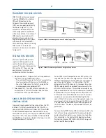
Bidirectional end-to-end BERT
Central Office
Customer Premises
Figure 12 Two-ended test on an IDSL Circuit
SSxDSL
w/IDSL Module
NT-
1
44K Mode
SSxDSL
w/IDSL Module
LT-
1
44K Mode
T
1
or
higher order
DLC
CO
Terminal
U-2B
1
Q
2-wire DSL
U-2B
1
Q
2-wire DSL
DLC
Remote
Terminal
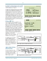
Ext. Clock
from DSLAM or
ISDN Switch
Bidirectional end-to-end BERT
Central Office
Customer Premises
Figure 13 Two-ended test on an IDSL Circuit over a DLC
to 2B+D in order to run the test at
the full rate of 144 kbps. An
external clock reference input for
the LT-144k unit on the CO side of
the circuit, is required if the circuit
goes through a DLC system.
The configuration of the test set
emulating the LT-144k mode is the
same as that shown in Figure 5.
The TX CLOCK is set according to
the requirement as detailed in the
Single-Ended Testing section. Refer
to Figure 10 for the configuration
of the test set emulating the NT-
144k mode.
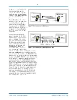
The T1/E1 SIG LED should turn
green, followed by the LP1 SYNC
LED after Layer 1 frame synchroni-
zation is acquired. If the circuit
goes through a DLC, enter the M4
ACCESS screen on the NT-144k
unit to confirm path continuity
between the two test sets. This
will allow you to observe the
status of the ACT bit (see Figure
11). If it is set to a 1, or if the ACT
indication is marked with an asterik (*), the circuit is
connected through the DLC to the DSLAM, or in this
case, the SunSet xDSL emulating the DSLAM (LT-144k).
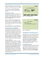
When set to 1, the end-to-end BERT test can be started
by going to the BERT & RESULTS screen. Check that the
PAT SYNC LED is solid green (indicating test pattern
synchronization) and that the BIT ERR LED is off on
both test sets. Inject a bit error from each of the test
sets by pressing the ERR INJ key on the keypad. The BIT
ERR LED should turn red for about one second and start
blinking red. Check that the ERROR COUNT reads one.
This verifies that the channel is properly looped back.
Press the HISTORY key to acknowledge the error
condition. You will notice that the BIT ERR LED will
stop blinking. Press the STOP/START F-key twice to
restart the BERT test. This will set the ERROR COUNT
back to 0 (refer back to Figure 7).