


2
© 2001 Sunrise Telecom Incorporated
SunSet xDSL: IDSL Circuit Testing
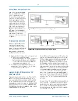
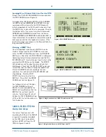
TRANSPORT FOR IDSL CIRCUITS
IDSL Circuits can be provisioned
from the DSLAM at the Central
Office (CO) location to the
Customer Premises Equipment
(CPE) over a copper pair directly
(as shown in Figure 1), if the
customer is located within the
reach range (about 18,000 feet
without repeaters). A number of
IDSL circuits can also be multi-
plexed and transported over a
Digital Loop Carrier (DLC) system,
which meets the Telcordia TR-
TSY-000397 requirement to bring
IDSL service to a cluster of
customers in the same area (refer
to Figure 2).
TESTING IDSL CIRCUITS
The turn-up of an IDSL circuit
requires verifying end-to-end
continuity and bit error perfor-
mance of the circuit between the
CO and the CP. There are two
possible ways to achieve the
verification test for the circuit:
• Single-ended test: Only one test set is required and
the circuit can be tested from either:
– The central office where the test set emulates the
Line Termination (LT) device, i.e. the DSLAM or,
– From the field where the test set emulates the
customer premises equipment (NT).
• Two-ended test: Two test sets are required, one
emulates the LT at the CO location and the other
emulates the NT at the CPE location.
SINGLE-ENDED TESTING FROM THE
CENTRAL OFFICE
In general, single-ended testing is done from the CO
location. A test set, emulating the LT at the CO, is
connected to the IDSL circuit under test. Then, ANSI
T1.601 embedded operations channel (eoc) loop up
commands can be sent to loop up the IDSL Router (NT/
TA) at the CP if it has been installed. A Bit Error Rate
Test (BERT) can then be run towards the loop, to verify
the performance of the circuit.
For an IDSL circuit transported over a DLC system, it is
required that the DLC be configured to use the 3-DS0
TDM multiplexing method to enable eoc commands to
pass through the system. In this method, the DLC
designates three DS0 channels to transport the entire
2B+D payload plus the overhead from one end to the
other end of the system. This method also enables eoc
loop commands to be sent to the channel unit cards (U-
BRiTE cards), which act as repeaters at either the DLC
CO Terminal or the DLC Remote Terminal. These loop
commands can help when troubleshooting the line
cards. If the DLC is set to run in Transparent mode, the
eoc channel will not be passed through the DLC to the
CPE and the loop commands will not be supported in
the DLC system. Therefore, a two-ended test must be
performed.
To successfully BERT test an IDSL circuit over a DLC, the
test set must be synchronized to the network clock to
avoid intermittent pattern sync loss due to clock slips.
This is detailed in the SunSet xDSL Application Series,
Publication Number APP-XDSL-010, IDSL Testing with
an External Reference Clock.
U-2B
1
Q
2-wire DSL
to ATM
backbone
Central Office
DSLAM
IDSL Router
NT/TA
Customer Premises
T
1
or
higher order
U-2B
1
Q
2-wire DSL
U-2B
1
Q
2-wire DSL
to ATM
backbone
DSLAM
IDSL Router
NT/TA
DLC
CO
Terminal
DLC
Remote
Terminal
Central Office
Customer Premises
Figure 1 IDSL Circuit transported over a 2-wire Copper Pair
Figure 2 IDSL Circuit transported over a Digital Loop Carrier