


3
© 2001 Sunrise Telecom Incorporated
SunSet xDSL: IDSL Circuit Testing
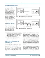
The single-ended tests from the
CO (Figures 3 and 4) are appli-
cable only if the CPE has already
been connected to the IDSL
circuit, or if the DLC system
supports and passes through the
eoc channel. If the eoc is sup-
ported, the SunSet xDSL with an
IDSL Module will be able to
loopback not only the CPE, but
also the channel unit line cards in
each of the DLC Terminals (CO and
Remote) for BERT analysis.
Configuring the Test Set
The configuration of the test set is
similar for testing an IDSL circuit
over a copper pair or over a DLC
system. The only difference is the
TX CLOCK setting. For testing
IDSL over a copper pair, the TX
CLOCK source should be set to
INTERN, to use the internal clock
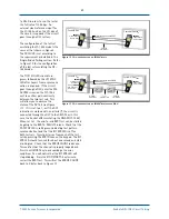
of the test set. However, for IDSL
circuits carried over a DLC, an
external reference clock should be
used to synchronize the test set to
the network. In most cases, a U
interface signal from either the DSLAM or an ISDN
switch is used, so TX CLOCK should be set to EXT-U (as
shown in Figure 5).
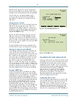
The TX CLOCK setting is only available when the test set
is configured to LT-144k. In this mode, the selected test
pattern is sent in the test channel specified. As you
cursor down to the TX CLOCK field, four F-keys will be
displayed. Select the appropriate clock setting that fits
the application to be run.
Connect the U-2B1Q connector of the test set to the
IDSL circuit under test and connect the U EXT CLK
connector to the external clock source, if applicable.
The TEST CHANNEL selection should be set to 2B+D to
BERT test the IDSL circuit at the full rate of 144 kbps.
You can also select a smaller set of channels to BERT
test at a lower speed.
The T1/E1 SIG LED should turn green, followed by the
LP1 SYNC LED after Layer 1 frame synchronization is
acquired. When the TX CLOCK field is set to EXT-U, the
FRAME LED will be used to indicate the status of the
external clock input. The FRAME LED will be solid green
to indicate a proper external clock signal, or will be red
if the external clock is not received properly.
T
1
or
higher order
Channel loopback
SSxDSL
w/IDSL Module
LT-
1
44K Mode
IDSL Router
NT/TA
DLC
CO
Terminal
U-2B
1
Q
2-wire DSL
U-2B
1
Q
2-wire DSL
DLC
Remote
Terminal
eoc loop up command
Central Office
Customer Premises
Figure 3 Single-ended test on IDSL Circuit from the CO
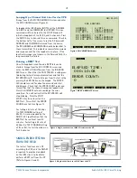
Figure 4 Single-ended test on IDSL Circuit transported over a DLC from the CO
TEST CONFIGURATION
INTERFACE : U
MODE : LT-144K
TEST CHANNEL : 2B+D
TEST PATTERN : 2047
INTERN EXT-T1 EXT-E1 EXT-U
08:11:01
TX CLOCK :
EXT-U
Figure 5 IDSL Module TEST CONFIGURATION Screen
SSxDSL
w/IDSL Module
LT-144K Mode
Ext. Clock
from DSLAM or
ISDN Switch
Central Office
IDSL Router
NT/TA
U-2B
1
Q
2-wire DSL
Channel loopback
eoc loop up command
Customer Premises