Sunrise Medical RGK HILITE User Manual Download Page 14

Hilite User Manual | Procedure 5

Hilite User Manual

UM-Hilite-020-EU

14

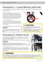
Procedure 5 - Castor Wheels and Forks

The castor wheels at the front of the wheelchair will wear just like care tyres and should be replaced when they visibly look 

worn or cracks appear.

5.1: Changing castor wheels

Using 2 x 4mm allen keys from the toolkit, remove 1 of 

the 2 screws in the centre of the castor wheel, as shown in 

Fig 9. Remove the screw and slide out the castor axle with 

the other screw still attached, noting any spacers and their 

positions. Install the new castor wheel and slide the castor 

axle back through and secure with the final screw.

5.2: Removing the castor fork

Remove cap at the top of the castor housing. Using the 

socket from the toolkit, release and remove the locking nut. 

This will release the castor fork, and take note of any spacers 

and their positions.

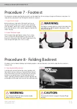
Procedure 6 - Wheel Locks

The wheel locks are adjustable in position to suit tyre changes and wear. As tyres 

wear, the wheel lock may not hold the wheelchair as intended, so these need to be 

adjusted to suit the tyre condition.

6.1: Adjusting Wheel locks

Using a 5mm Allen key from the toolkit, release the 2 screws in the clamp or on the 

underside of the plate. Once the wheel lock is loose, reposition so that there is at least 

3mm of interference when the wheel lock is activated. Tighten securely and repeat 

on the other side.

Procedure 5 & 6

NOTE:

Castor Bearings must be fitted by an authorised dealer. 

Failure to do so will result in invalid warranty on the 

parts.

CAUTION:

DO NOT replace the front castor forks or castor wheels 

with a different size other than what was originally 

supplied on the chair.

By changing to a different size castor fork or castor wheel 

will have an adverse effect on the running of the chair 

and the end users balance causing personal injury.

NOTE:

Before adjusting or replacing any style of wheel lock ensure that the tyres are 

inflated to the recommended pressure as indicated on the tyre. 

WARNING:

After any adjustments, repair or service and before use, make sure all attaching hardware is tightened securely – otherwise 

injury or damaged may result. If wheel locks do not hold occupied wheelchair in place please adjust as above, or contact 

your dealer – otherwise injury or damages may occur. The wheel locks are designed to work when your wheelchair is static. 

Wheel locks should not be applied during use and tyre pressure should be as indicated on the tyre.

Fig 9.

Fig 10.

Fig 11.

Summary of Contents for RGK HILITE

Page 1: ...User Manual Hilite User Manual UM Hilite 020 EU WHEELCHAIR DIRECTIONS FOR USE EN...

Page 2: ...ttach the wheels and separate parts 4 Check everything is as expected and that all parts are secured functioning and set up correctly including tyre pressure 5 Adjust the upholstery ensuring it provid...

Page 3: ...n every detail exactly to your own model However all instructions are completely relevant regardless of possible detail differences The manufacturer reserves the right to alter without notice any weig...

Page 4: ...Hilite User Manual UM Hilite 020 EU 4 A BACKREST B WHEEL LOCKS C REAR WHEELS D CASTOR WHEELS E CASTOR FORKS F FOOTPLATE G FOOTPLATE COVER H CAMBER AXLE I FRAME J UNDER SEAT BRACE BAR K CUSHION COVER...

Page 5: ...vide maximum safety International safety standards currently in force have been fulfilled where appropriate Nevertheless users may put themselves at risk by improperly using their wheelchairs For your...

Page 6: ...as a weight training apparatus This product has NOT been designed or tested as a seat for any kind of weight training If occupant uses said wheelchair as a weight training apparatus RGK shall NOT be...

Page 7: ...r light clothing or clothing with reflectors so that you can be seen more easily Make sure that the reflectors on the side and back of the wheelchair are clearly visible We would also recommend that y...

Page 8: ...and injuries do not grab in between the spokes or between the rear wheel and wheel lock when driving the wheelchair Do not use the wheelchair on slopes 5 The dynamic safe slope is dependent on the cha...

Page 9: ...tight Front Castor Inspect wheel fork assembly for proper tension by spinning castor castor should come to a gradual stop Loosen tighten locknut if wheel wobbles noticeably or binds to a stop Wheel b...

Page 10: ...e ness in chair Solutions Check tyres for correct and equal pressure Check for loose castor stem nuts Check all fixtures are secure and tight Check spokes for tension Check that both castors contact t...

Page 11: ...is adjusted by increasing or decreasing the tension on the straps at the back of the backrest To remove release all the straps and remove 1 3 Changing Cushion Cover Remove cushion from the wheelchair...

Page 12: ...k release axle pin Only adjust the quick release axle pin if the wheel does not engage or the wheels feels loose To adjust the length remove the axle pin from the wheel and by using 2 x adjustable spa...

Page 13: ...be causing a puncture Procedure 4 Camber Bar The Camber Axle or Camber Tube control your wheel position and your centre of gravity It is very important to have this set up for your requirements for pe...

Page 14: ...rom the toolkit release the 2 screws in the clamp or on the underside of the plate Once the wheel lock is loose reposition so that there is at least 3mm of interference when the wheel lock is activate...

Page 15: ...osition to the correct angle and tighten the screws securely Procedure 8 Folding Backrest The backrest can be fixed or folding and if a folding option is chosen the backrest can fold to make the chair...

Page 16: ...2 Screw in push handles Screw in push handles can be removed by unscrewing them from the back rest To install screw them in until tight by hand 9 3 Operating flip down push handles Press the button u...

Page 17: ...the same way To adjust the length press the button on the tube and lengthen or shorter the wheel tube 10 2 Single sport anti tip To remove anti tip remove quick release pin and remove tube The clamp a...

Page 18: ...emove sideguards from receiver Using a 4mm allen key from the toolkit release the 2 screws securing the sideguard to the lift out post To install replace and tighten the 2 screws Take care not to cros...

Page 19: ...l not provide the equivalent of safety and security as a vehicle seating system We recommend that the user transfers to the vehicle seating It is recognised that s this is not always practical for the...

Page 20: ...ility uphill N A 5 of incline Static stability sideways N A 5 of incline Seat plan angle 0 45 of tilt Effective seat depth 250mm 500mm Seat surface height at front edge 380mm 550mm Backrest angle 10 o...

Page 21: ...Fixings Wheel Locks Footplate covers Titanium Frame Castor Forks Quick release axle Fixings Side guards Anti Tippers Frame Footrest Plastic Handles Tube stoppers Castors Footplate covers Arm pads Pac...

Page 22: ...ar H Product Description or inside the backrest upholstery A Please provide the following information whenever you have to order replacement parts Serial Number Name Dealer Identification sticker Loca...

Page 23: ...aired or exchanged within the scope of this warranty we provide a warranty in accordance with these warranty conditions for the remaining warranty period for the wheelchair in accordance with point 1...

Page 24: ...Medical com RGK Wheelchairs LTD Unit 8 A B C Ring Road Zone 2 Burntwood Industrial Estate Burntwood Staffordshire WS7 3JQ UK Call 44 0 1543 670 077 Email info rgkwheelchairs com Sunrise Medical GmbH K...

Reviews: