2 Issue 4
30
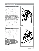
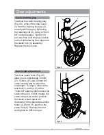
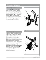
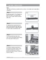
Fig. 39
Fig. 38
Chair adjustments
Scissor locks
To adjust low mounted wheel locks
the two retaining screws (1) must
be loosened a ¼ turn at a time,
using a 5mm A/F Allen key,
alternating between the two screws
until the clamp (2) can slide along
the frame tube (3). The grip bar (4)
must embed into the tyre (5)
approximately 4mm (3/16") to be
correctly set. When the correct
setting is achieved tighten the
retaining screws ¼ turn at a time to
a torque setting of 15Nm (Fig. 38).
5
Centre of gravity
The centre of gravity (Fig. 39) is
adjusted by moving the axle sleeve
(1) backward or forward on the
indexed axle plate (2). To move the
axle sleeve undo the outer 28mm
A/F retaining nut (3) sufficiently to
allow the locking washer (4) and
the axle sleeve assembly to slide in
the axle plate, find the desired
index slot (5) and tighten the
retaining nuts to 45Nm torque.
Note:
After changing the centre of
gravity always check:-
Toe in/toe out (Fig. 43, page 32)
Angle of castors (Fig. 46,
page 34) Both axles are in
identical positions.
1
2
5
4
1
2
3
4
3

