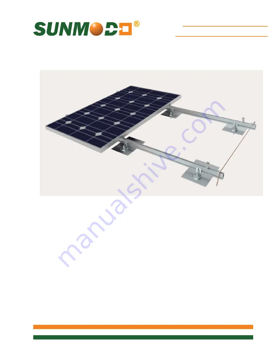
Pitched Roof Mount System
With Self-grounding Hardware
Pub. D10004-V010
Copyright 2015
EZ Roof Mount System With Self-grounding Hardware
UL2703 Compliant
Page 1: ...Pitched Roof Mount System With Self grounding Hardware Pub D10004 V010 Copyright 2015 EZ Roof Mount System With Self grounding Hardware UL2703 Compliant ...
Page 2: ...CONTENTS Installer Responsibility 3 Safety 3 SunModo Self Grounding System 4 EZ Roof Mount System Components 5 List of Compliant PV Modules 7 Tools Required for Installation 10 EZ Roof Mount System Installation 11 Torque Values of EZ Roof Mount Components 12 Panel Configurations 13 EZ Roof Mount Installation 15 Helio Rail Installation 17 Panel Clamp Installation for Portrait Mounting 20 Panel Clam...
Page 3: ...EZ Roof Mount System over a Fire Resistant roof covering rated for the application Installer is responsible to determine that the roof its rafters connections and other architectural support components can sustain the array under all code level loading conditions The installer shall comply with all applicable local or national building codes including periodic re inspection of the installation for...
Page 4: ... system is our patented stainless steel floating grounding pin which is designed to be captive in the mounting components and provides a bonding path from the PV panel frames to the rails and rail splices and finally to the ground lug Fig 1 Mid Clamp with Ground Pins Fig 1 shows the grounding pin and the location within the mid and end clamps Similarly the rail splices in Fig 2 include the groundi...
Page 5: ...ff Helio Rails Features both 1 4 and 3 8 side slots and 1 4 top slot for clamping PV panels Last 3 digits denote length 4 stock sizes in clear and black Table 1 A20144 XXX Standard Rail A20145 XXX Heavy Rail 3 8 Slot Rail Splice Kit with 2 3 8 16 hex bolts and flange nuts with integral grounding Maybe repositioned until torqued to final value K10178 001 For single use only 1 4 Slot Rail Splice Kit...
Page 6: ...d to final value K10183 XXX For single use only Landscape Mid Clamp Kit with adaptor for standard rail and integral grounding fits panel height from 31 to 50 mm For last 3 digits see Table 4 Maybe repositioned until torqued to final value K10182 XXX For single use only Grounding Lug Kit with Grounding Spacer and 1 4 20 T Bolt Maybe repositioned until torqued to final value K10179 001 For single us...
Page 7: ...n Solar CS6X 300P CS6X 305P CS6X 310P CS6X 315P CS6X 320P CS6P 255P CS6P 260P CS6P 265P CS6P 260M CS6P 265M CS6V 210P CS6V 215P CS6V 220M CS6V 225M CS6K 265M CS6K 270M ET Solar ET P672300WW ET P672305WW ET P672310WW ET P672315WW Hanwha Q Cells Q PRO L G2 305 Q PRO L G2 310 Q PRO L G2 315 Hareon HR 280P 24 Ba HR 285P 24 Ba HR 290P 24 Ba HR 295P 24 Ba HR 300P 24 Ba HR 305P 24 Ba HR 310P 24 Ba Itek E...
Page 8: ...285W mono 280W mono 275W mono 270W mono 265W mono 260W mono 255W mono 250W mono Sunmodule Protect 275W mono Sunmodule Protect 270W mono Sunmodule Protect 265W mono Sunmodule SW 245 255 poly Pro Series SolarWorld 33mm frame Sunmodule Pro Series 250W poly 255W poly 260W poly 315W XL mono 320W XL mono 325W XL mono Sunmodule Plus 260W mono 270W mono 275W mono 280W mono 285W mono Stion STO 135A STO 140...
Page 9: ... With Self grounding Hardware 9 of 24 SunPower X21 355 BLK X21 345 SPR E20 327 SPR E19 320 Trina TSM 225 PC PA05 TSM 230 PC PA05 TSM 235 PC PA05 TSM 240 PC PA05 TSM 245 PC PA05 Yingli YL230P 29b YL235P 29b YL240P 29b YL245P 29b ...
Page 10: ...ation Electric Drill or impact driver Note that the use of an impact driver is strongly discouraged for all stainless nut and bolt hardware Roofing Bar Drill Bit for lag bolts pilot hole 7 32 diameter for 5 16 lag bolt 3 8 Socket wrench Sockets for 3 8 drive sockets 7 16 1 2 9 16 and 1 1 16 ...
Page 11: ...rdware 11 of 24 Torque Wrench 3 8 drive 0 to 35 ft lbs Anti seize compound Permatex 80071 or equivalent Caulk gun and silicon sealant Chem link M1 construction sealant or equivalent Tape measure Saws for cutting aluminum posts and rails as necessary ...
Page 12: ...quired that a torque wrench be used to measure the bolt torque during final assembly and it is recommended that anti seize compound be applied to the screw threads Table 3 Torque Values for EZ Roof Mount Components Hardware Torque 1 4 Bolts and Hex Flange Nuts 7 5 ft lbs 3 8 Bolts and Hex Flange Nuts 15 ft lbs 3 8 T bolts and Hex Flange Nuts 15 ft lbs Mid or End Clamp 1 4 20 Female Standoff with 7...
Page 13: ...PV Systems using the Self grounding Mid Clamps Fig 3 Self grounding PV System Portrait Fig 3 details a typical portrait roof layout featuring two East West rails mounted to North South roof rafters with an L foot Detail C shows the use and position of Mid Clamps Module length is shown as a nominal 60 cell PV panel however longer 72 cell PV panels can also be used ...
Page 14: ...rail to be adapted to share rail use for landscape layout of roof mount PV systems Note that the PV panels are clamped on the long edges as required by most manufacturers This share rail adaptor system is shown in Fig 5 Note that the self grounding feature is present on mid clamp Fig 5 Mid and End Clamps with Rail Adaptors The self grounding adaptors fit into a Standard or Heavy rail allowing inst...
Page 15: ...he hole should not be more than 3 in depth and a drill stop may be used to insure this Fig 6 Locate lag screw mounting Drill a 7 32 hole through the shingle to a depth of 2 inches Clean sawdust with drill and fill hole with sealant Use the 4 inch by 5 16 lag bolt supplied to install the aluminum roof shoe Use Chem link M1 Construction Sealant or Equivalent Fig 7 After filling the hole with sealant...
Page 16: ...shaped bead of sealant can be added under the flashing if the installer is concerned with water migration Fig 8 Slide the roof flashing into place under the overlapping shingle and over the threaded portion of the roof shoe Insert L Foot onto the large thread on the roof shoe on top of flashing Place aluminum hex cap on shoe and finger tighten the cap Then tighten to 15 ft lbs nominal torque Fig 9...
Page 17: ...lt Install AL rail to L Foot to the specific orientation desired Tighten 3 8 flange nut to 15 ft lbs and 1 1 16 aluminum hex cap to 20 ft lbs torque Minimum leading edge height to meet a UL1703 PV module fire standard is 3 inches Fig 11 Aluminum Rail Attached Fig 12 PV Module Attached 3 inch minimum from bottom of PV module frame to the roof covering ...
Page 18: ...e 1 4 rail slots can be used Shown is the 2 bolt 3 8 rail slot version which must be torqued to 15 ft lbs Fig 13 The 2 bolt splice can be used to join rail section together The 4 bolt version of the rail splice can also be used Torque on the 1 4 flange nuts is a maximum of 7 5 ft lbs Fig 14 A 4 bolt version of the self grounding splice can be installed to join rail sections together ...
Page 19: ...K10224 046 K10180 157 46 mm 1 57 B20015 013 Portrait K10224 050 K10180 210 50 mm 2 10 B20015 002 Clamps Part End Part Mid Size T Bolt in T Bolt PN Landscape K10183 031 K10182 157 31 mm 1 57 B20015 013 Landscape K10183 033 K10182 157 33 mm 1 57 B20015 013 Landscape K10183 040 K10182 157 40 mm 1 57 B20015 013 Landscape K10183 042 K10182 210 42 mm 2 10 B20015 002 Landscape K10183 044 K10182 210 44 mm...
Page 20: ... collar nut onto the top of the T bolt as shown in Fig 14 below After positioning the end clamp firmly against the PV panel frame tighten to 7 5 ft lbs Fig 15 End Clamp Collar Nut and T Bolt Fig 16 Ground wire mounting options Installing Mid Clamps A mid clamp is used between PV panels and produces a 1 2 spacing between PV panel frames Insert the T bolt in the rail slot and turn clockwise 90 degre...
Page 21: ...itioning the end clamp firmly against the PV panel frame tighten to 7 5 ft lbs Fig 19 End Clamp Collar Nut and T Bolt Fig 20 End Clamp Installed Installing Mid Clamps A mid clamp is used between PV panels and produces a 1 2 space between PV panel frames Insert the T bolt in the rail slot and turn clockwise 90 degrees to a engage the head into the rail slot and b ensure the rail adaptor drops into ...
Page 22: ... ground lug for fastening the ground conductor to the array The lug is mounted on the top of the rail using a special 1 4 T bolt conducting washer and flange nut A detailed Grounding Lug installation document is available from SunModo separately Fig 24 Grounding Lug Fig 25 Mounting Grounding Lug Fig 26 The picture shows a grounding lug mounted on each rail and a 6 solid copper grounding wire conne...
Page 23: ...ed properly in accordance with SunModo s Written Installation instructions or is not used for the purpose for which it is designed or the product has been modified repaired or reworked not authorized by SunModo The limited warrantee is void if the system installation is not periodically inspected for loose components fasteners and corrosion and if any are found the affected components are not imme...
Page 24: ... of a specified Party or any other person that has obtained or hereafter obtains rights or interests from such party This Warranty constitutes the entire integrated agreement between SunModo and Purchaser concerning the Product warranties and supersedes all prior agreements and discussions and the terms or any purchaser orders order acknowledgements or similar documents No agreement or understandi...