background image


SunMaxx Solar LLC


Page 4 of 39 


SOLAR WATER HEATER PACKAGING & TRANSPORT 

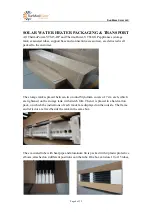
All ThermoPower-VTS15-HP and ThermoPower-VTS30-GP appliances (storage 
tank, evacuated tubes, support base and connection accessories), are delivered well 
packed to the customer.


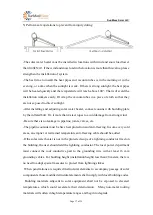
The storage tank is placed between two round Styrofoam covers of 7 cm each, which 
are tightened on the storage tank with stretch film. Then it is placed in a hard carton 
pack, on which the indications of each model are displayed on the outside. The frame 
and reflector are fixed beside the tank in the same box.


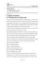
The evacuated tube with heat pipe and aluminum fin is packed with 4 plastic protective 
elbows, attached on 4 different positions oon the tube. One box can store 10 or 15 tubes, 
and are then packed in a wooden box. 


Summary of Contents for ThermoPower-VTS15-HP Series

Page 1: ...hermoPower VTS30 HP E ThermoPower VTS15 HP TG ThermoPower VTS30 HP TG ThermoPower VTS15 HP TE ThermoPower VTS30 HP TE The solar energy system described by this manual when properly installed and maintained meets the minimum standards established by the SRCC This certification does not imply endorsement or warranty of this product by SRCC The supplier s name SunMaxx Solar LLC ...

Page 2: ...nti freezing protections 10 4 5 Specific notices 10 5 Installation of solar water heater 12 5 1 Frame installation drawing 12 5 2 Installation of frame 13 5 3 Installation of the tank 14 5 4 Installation of the heat pipe and vacuum tubes 14 5 5 Solar water heater installation and attention 15 6 Pipeline installation 18 6 1 Plumbing system schematic map 18 6 2 Plumbing connections 23 6 3 Pipe Insul...

Page 3: ...ufacturer s instructions Children should be supervised to ensure they DO NOT play with the appliance In order to prevent from burn injury touching the heat pipes in the glass tubes is strictly prohibited The evacuated tubes should not be exposed to direct sunlight before installation Care should be taken not to touch the pipe work as it may be HOT Plastic pipe is NOT suited to the water temperatur...

Page 4: ...wo round Styrofoam covers of 7 cm each which are tightened on the storage tank with stretch film Then it is placed in a hard carton pack on which the indications of each model are displayed on the outside The frame and reflector are fixed beside the tank in the same box The evacuated tube with heat pipe and aluminum fin is packed with 4 plastic protective elbows attached on 4 different positions o...

Page 5: ...round midday Year round utilization even in cold windy climates where freezing does not occur below 2 degrees Celsius for short periods of time Can operate with incoming water pressures of 0 4 MPa no circulating pump or controller necessary The system will still function even if some vacuum tubes lose their vacuum or are accidentally damaged All day tracking capabilities due to 360 absorber on inn...

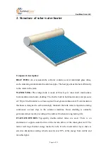
Page 6: ...Shell material is corrosion proof food grade stainless steel Foam insulation thickness is designed to self sustainingly maintain the tank water temperature during continuous overcast days in the coldest wintertime Outer cladding is normally galvanized sheet metal providing a fine surface finish and a long lasting life EVACUATED TUBES Top quality double walled tubes are used There is an aluminum or...

Page 7: ...rame may have full length rear legs suitable for flat surface installation or shortened rear legs suitable for sloped surface installation Length of rear legs could be cut to fit at site 3 Working principle 3 1 Principle of vacuum tube The vacuum tube is composed of inner tube outer tube selective absorption layer vacuum space inspiratory layer The outer wall of the inner tube is the selective abs...

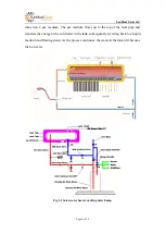
Page 8: ...lows up to the top of the heat pipe and transfers the energy to the cold water in the tank subsequently reverting back to a liquid medium and flowing down As the process continues the water in the tank will become the hot water Fig 3 1 Solar water heater working sketch map ...

Page 9: ...nsulation Polyurethane 55mm Polyurethane 55mm Stagnation Temperature 220 220 Maximum working temperature 90 90 Maximum Working Pressure of all circuits 0 6MPa 0 6MPa Working pressure 0 4MPa 0 4MPa Maximum wind and snow load 0 49kN m 0 49kN m Tilt Angle 45 45 Inlet and Outlet in in T P Valve Port in in Frame Aluminum Alloy Aluminum Alloy 4 2 System Tolerance Information Freeze tolerance limits are ...

Page 10: ...perature is lower than 14o F to avoid freezing in the connecting pipe In case of black out or power loss during cold weather when the temperature is lower than 14 F or 10 Celsius a system drain out procedure must be followed as follows and the existing auxiliary water heater must have adequate capacity listed and labeled by an accredited listing organization to continue providing adequate hot wate...

Page 11: ...king observe the thermometer when hot water is being used in the house The water returning from the collector on a sunny day should be at least 10 F warmer than the water going up to the collector The temperature of the cold water and hot water is displayed on the monitor 4 5 5 The insulation of the final 5 feet to the auxiliary water heater GUIDE 6 1 6 3 The insulation of the final 5 feet to the ...

Page 12: ...pipes should be insulated with R2 6 with thickness at least 1 4 4 5 11 Projected components need to be replaced The glass vacuum tubes might need to be replaced if broken by unexpected hazards such as collision with a hard material Please contact the installer to order replacement parts The battery of the temperature monitor needs to be replaced when the battery is out The battery can be purchased...

Page 13: ...e 13 of 39 1 back box 2 adjusted end cap 3 front pole 4 front support 5 tank bracket 6 horizontal support 5 2 Installation of frame 1 front pole and rear pole installation 2 rear level bar and rear support bar installation ...

Page 14: ...the installed frames slowly and lightly Take care to insert the bolts of the water tank into the corresponding connecting holes of the tank brackets Step 2 Install the accessories and turn the small red cap of the air vent on the top to ventilate Step 3 Install the T P valve 5 4 Installation of the heat pipe and vacuum tubes Open the pack of vacuum tubes and take out one vacuum tube at a time a In...

Page 15: ...r GPS wait until solar noon and the shadow of a vertical stick or surface will point due North True South is 180 from true North HINT MANY SOLAR SYSTEMS ARE PLACED AT THE ROOF SLOPE WHICH IS LESS THAN LATITUDE MINUS 15o BUT IS MORE AESTHETICALLY PLEASING WITH ONLY A SMALL 10 PENALTY IN ANNUAL PERFORMANCE The latitude of your location can be found on the Internet or in your local paper The latitude...

Page 16: ...s TN 35 Los Angeles CA 34 Phoenix AZ Charleston SC 33 San Diego CA Savannah GA 32 Houston TX New Orleans LA Jacksonville FL 30 Tampa FL 28 Brownsville TX Miami FL 26 Honolulu HI 21 Hilo HI 20 Three reference poses are given below However in deciding the specific location and pose of a unit the installer should consider 1 Choose a strong foundation and safe place 2 Location should have optimized su...

Page 17: ...ong wind Be sure there is no leakage in pipeline joints valves etc The pipeline outside must be have heat protection and anti freezing In some very cold areas an emptier or restrained temperature anti freezing cable should be added If the solar water heater is not in the protected scope of a lightning conductor fixed on the building the user should add the lightning conductor The local power depar...

Page 18: ...currently Set the output water temperature at a point of 48 9o C 120o F The tank upper temperature limit is 300 F and 130 psig As the thermosiphon system has no way to stop the operation of the solar collector there should always be a T P relief valve installed to release some high temperature water out of the tank then mains water will charge the tank to keep the tank in normal working condition ...

Page 19: ...elow is the installation pipe line of pressurized solar water heater The directions of each valve and the corresponding positions should match the illustration There should be no leakage in the tie in The pipe line must have heat preservation and anti freezing Underground piping subject to vehicular traffic shall be installed to withstand the additional load applied by this traffic The trenches an...

Page 20: ...chitect and signed by licensed plumbers Acquire the proper working permits from the local city building department before the installation Install the system using a licensed contractor with solar install certificate Request and perform the inspection and sign off after installation Important Notice and Warnings To prevent burn injury touching the heat pipe in the glass tubes is strictly prohibite...

Page 21: ...nk to measure the temperature accurately Method 2 if the sensor pocket is not available when installing the system you can choose this easier method to install the temperature sensor step1 Put the temperature sensor close to the inlet and outlet copper pipe Keep them tightly in contact Fig2 Use duct tape to fix the sensor Fig3 Then insulate the whole pipe with PU foam The sensor shall be install a...

Page 22: ... least 10 F warmer than the water going up to the collector The temperature of the cold water and hot water is displayed on the monitor The monitor main unit shall work normally with ambient temperature between 10 C and 60 C and humidity under 90 RH The thermal sensor shall meet the working temperature between 40 C 110 C The recommended measure accuracy is 0 1 C If the solar water heater is instal...

Page 23: ...nd Valve labels ID Name Normal operation position Model technical specification Photo Quantity V0 City water shut off valve ON 3 4 ball valve 1 V1 Solar Bypass valve OFF 3 4 ball valve 1 V2 Solar isolation valve ON 3 4 ball valve 1 V3 Solar isolation valve ON 3 4 ball valve 1 ...

Page 24: ...Set temperature 48 9 C 1 2 WATTS series 70A Tempering Valve 120 F 160 F temperature range 120 F to 160 F Maximum Pressure 150psi 10 bar Size Range 1 2 to 3 4 in 15 to 20mm 1 V7 T P R valve Normal operation condition WYA 15 1 2 Meet ANSI Z21 22 Inlet 1 2 in tapered male thread Outlet 1 2 in parallel fe male thread Maximum opening temp erature 90 99 Rated working pressure 0 4MPa 0 6MPa Maximum worki...

Page 25: ...onal sanitation foundation Connection 2 3 4 CxCxC Tee and Couplings Cooper 3 4 Materials shall meet the standards of the National Sanitation Foundation Connection 3 3 4 Copper x Female Adapter Cooper 3 4 Materials shall meet the standards of the National Sanitation Foundation V8 Air vent valve OPEN R99Y 1 V9 No return valve check valve OPEN Maximum operating pressure 400psi 1 ...

Page 26: ...er fluid identity and AWWA class 1 warning that fluid may be discharged at high temperature and or pressure Unauthorized alterations to this system could result in a hazardous health condition Solar Isolation Valve OPEN V2 Solar Bypass Valve Normal Operation Position CLOSE City water shut off valve Shut this valve will shut the water supply for the solar and Hot Water System Normal operation posit...

Page 27: ...d or hung on the valves installed according to the diagram in this manual 6 3 Insulate the pipe For the installation of the pipeline system and power cord including indoor and outdoor parts of the flat solar system the pipeline shall go through the airway of the house and should not be installed in the flue the indoor part shall be open line and shall not bury Heat transfer fluid identity and AWWA...

Page 28: ... insulation that can be used on any type of pipe each with its one unique advantages and disadvantages First there is spiral wrap fiberglass insulation which is the cheapest of all the options but also has the lowest R value of the group as well as the most labor intensive to install Second is self sealing foam tubing This kind of foam pipe insulation has been found to be extremely easy and quick ...

Page 29: ...s under stagnation conditions 2 The specification of the chosen insulation material should be checked with the insulation manufacturer prior to installation as different materials may vary in temperature tolerance 3 The outdoor pipes should be insulated with R6 6 insulation with thickness greater than or equal to 1 inch The indoor pipes should be insulated with R2 6 with thickness at least 1 4 4 A...

Page 30: ...ith minimum outside exposure length It should be lined up through the attic and interior walls However in case it is hard to wire through interior walls the pipes can run along an external wall and enter at the basement level All plumbing work must be carried out by a qualified person and the material of the collector loop shall conform to local authority requirements 7 Commissioning the system ...

Page 31: ...pe connecting the T P valve hole in order to allow steam caused by high temperature and pressure of the system to escape in such a way that no damage is done to the system or any other materials in the building by the drained hot water For information on regular operation of safety valves please see the user guideline in the packing of safety valves 4 The system must be maintenance by a specialist...

Page 32: ...pened or you will leave the solar system unattended and unused for long periods of time please turn off V2 and V3 and open V1 If after using this trouble shooting guide you still can t solve the problem please contact your authorized service provider 9 Maintenance requirements 9 1 Cleaning Regular rain should keep the evacuated tubes clean but if particularly dirty they may be washed with a soft c...

Page 33: ...m tubes from breaking due to substantial difference in temperature 2 In order to avoid scalding please turn on the cold water valve first then turn on the hot water valve then adjust the cold water valve and hot water until reaching the suitable hot water temperature if the mixing valve is not available 3 In area where water pressure is high please turn down the filling water valve so cold water c...

Page 34: ... of the solar geysers the dealer responsible for the sale will fill out the warranty card and the customer will complete a record of it and retain it for future servicing This limited warranty covers the glass tubes hot water tank and tank support frame for tube breakage leakage or any other malfunction caused by defects in the materials and or workmanship It extends to the first buyer and to any ...

Page 35: ...pping or delivery charges removal installation or re installation charges any materials and permits required for installation re installation or repair All legal disputes to be settled in New York State To facilitate warranty service you should Follow all instructions enclosed with the product Retain all bills of sale or receipts for proof of installation etc Contact your installer or dealer as so...

Page 36: ...1 Evacuated tube with heat pipe and aluminum 30 2 2 Sealing gasket 30 3 3 Tank 1 4 4 T P relief valve 1 5 5 Automatic air vent 1 6 6 Horizontal support 4 7 7 front support 4 8 8 Adjusted end cap 30 9 9 End bracket 1 10 10 Bolt nut 25 11 11 Tank support 3 12 12 Front leg 3 The part No in this table shall be refer to the No in the below drawing ...

Page 37: ... 13 Ball valve 3 4 3 14 Non return valve 1 15 Drain valve 3 4 2 16 Copper Pipe 3 4 The length determined by the actual layout 17 Temperature monitor 1 18 TEE Coupling 3 4 Per the actual install conditions 19 Pipe insulation 2 Per the actual install conditions 20 Pipe insulation 3 4 Per the actual install conditions 21 PVC pipe 4 Per the actual install conditions 22 Mixing valve 1 23 Back up water ...

Page 38: ...ter Consumer are free to choose any other 50 gallon gas or electric water heaters with R value equal to or greater than 16 and with volume within 10 of 50 gallons ANNEX 2 Notice Label Hot warning label Freeze protection label Freeze Protection Information The freeze protection method of this system is thermal mass and manual draining Drain the system as instructed in the owner s manual when temper...

Page 39: ...x Solar LLC 5042 5160 New York 206 Bainbridge NY 13733 USA Solar Energy Factor SEFD SRCC Cert No Model No 0 7 1 2 0 9 1 4 1 3 1 0 1 7 1 4 30004234 30004235 30004236 30004237 30004249 30004250 30004251 30004252 VTS30 HP G VTS15 HP G VTS15 HP E VTS30 HP E VTS30 HP TG VTS15 HP TG VTS30 HP TE VTS15 HP TE The installed system is marked above ...

Reviews: