background image

54

-- -- E

En

nd

d

9.10.12 Third-party portal

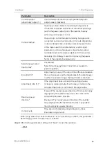
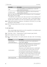
Configure the third-party cloud forwarding service for the Logger3000 on this interface.

step 1

Click "System" -> "Transfer configuration" -> "Third-party portal" to enter the
corresponding interface.

step 2

Turn on the switch.

step 3

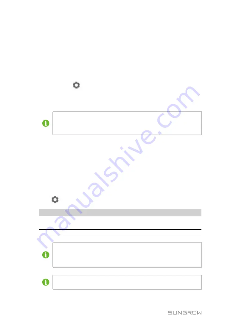
Click the button

on the operation bar, so that an advanced setting window will

pop up.

step 4

Modify the configuration information and click "Save".

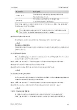
Set the FTP path and name it as "/FTP server directory".

For example, for the name "/SUNGROW", / is the root directory, and

SUNGROW is the directory where data is stored on the FTP server.

-- -- E

En

nd

d

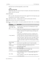
9.10.13 Interface

Set ports of the Logger3000 on the interface. There are 6 RS485 ports (COM1~COM6)

and 1 PLC port.

9.10.13.1 RS485

step 1

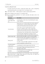
Click "System" -> "Interface" -> "RS485" to enter the corresponding interface.

step 2

Click

to modify baud rate, parity bit, and stop bit.

S

Se

erriia

all P

Po

orrtt

B

Ba

au

ud

d R

Ra

atte

e

C

Ch

he

ec

ckk B

Biitt

S

Stto

op

p B

Biitt

P

PL

LC

C A

Ac

cc

ce

essss

COM1~COM6

9600

Null

1

Disable/

Enable

PLC

115200

Null

1

Enable

When a serial port of Logger3000 is connected to a device, the "Baud rate", "-
Check bit", and "Stop bit" of the serial port must be configured the same as
those of the corresponding device, so as to ensure normal communication
between Logger3000 and the device.

When "PLC Access” corresponding to COM1~COM6 is set to "Enable", the
baud rates of COM1~COM6 will be automatically changed to 115200.

9 Web Interface

User Manual

Summary of Contents for Logger3000

Page 1: ...at ta a L Lo og gg ge er rU Us se er r M Ma an nu ua allL Lo og gg ge er r3 30 00 00 0 U UE EN N V Ve er r2 20 0 2 20 02 20 00 02 2 Logger3000 UEN Ver20 202002 Logger3000 D Da at ta a L Lo og gg ge e...

Page 2: ......

Page 3: ...lation Flow 11 5 Unpacking and Storage 13 5 1 Scope of Delivery 13 5 2 Identifying the Logger3000 14 5 3 Checking upon Receiving 14 5 4 Storage 15 6 Mechanical Installation 16 6 1 Location Selection 1...

Page 4: ...ioning 34 8 1 Inspection before Commissioning 34 8 2 Commissioning Steps 34 9 Web Interface 36 9 1 Running Requirements 36 9 2 Login Steps 36 9 3 Web Main Interface 37 9 4 Web Menu 37 9 5 Operation Pr...

Page 5: ...54 9 10 14 More 56 9 10 15 About 56 10 Grid Dispatching 57 10 1 Function Description 57 10 2 Power Regulation 57 10 2 1 Active Power 57 10 2 2 Reactive Power 64 10 2 3 Emergency Button 69 11 Maintena...

Page 6: ......

Page 7: ...miliar with the PV grid connected power generation system and its working principle Have received professional training in installing and commissioning of the electrical devices Be capable of handling...

Page 8: ...from the sources Check user manual before service S Sy ym mb bo olls s This manual contains important safety and operational instructions that must be accurately understood and respected during the i...

Page 9: ...erforming operation on the device This manual must be stored at hand and available at all times All rights reserved including the pictures symbols and markings used in this manual Any reproduction or...

Page 10: ...work related safety warnings and notes will be specified at the critical points in corresponding chapter All operations and electrical work must only be performed by qualified personnel B Be ef fo or...

Page 11: ...e Logger3000 can only be performed by qualified personnel from SUNGROW or other qualified personnel User can never maintain or replace the modules and other parts Serious personal injury or property l...

Page 12: ...ogger3000 D Da at ta a F Fo or rw wa ar rd diin ng g S Se er rv viic ce e The Logger3000 can forward collected data to cloud platform for example iSolarCloud P Pr ro ot to oc co oll C Co on nv ve er r...

Page 13: ...arrier communication bus The Logger3000 sends the collected data to Insight or a third party server via a core switch and then the background sends the data to iSolarCloud through a router C Co on nn...

Page 14: ...8 f fiig gu ur re e 3 3 2 2 Star networking 3 Product Introduction User Manual...

Page 15: ...e of the Logger3000 is shown in the following figure N No o D De es sc cr riip pt tiio on n A Indicator B Mounting ear C Wiring terminal I In nd diic ca at to or r I In nd diic ca a t to or r N Na am...

Page 16: ...N Na am me e D De es sc cr riip pt tiio on n BLE Bluetooth indicator Reserved FAULT Fault indicator On fault occurs in connected inverter Off connected inverter is free of fault 3 3 2 Dimensions 3 Pr...

Page 17: ...er r 1 Unpacking and inspection 5 1 Scope of Delivery 2 Read the user manual especially Safety Instructions 2 Safety Instructions 3 Store the Logger3000 properly if it is not to be installed immediate...

Page 18: ...Pr ro oc ce ed du ur re e R Re ef fe er re en nc ce e c ch ha ap pt te er r 7 Check before commissioning 8 1 Inspection before Commissioning 8 Commissioning 8 2 Commissioning Steps 4 Installation Flow...

Page 19: ...tificate packing list product test report and warranty card C Communication terminal resistor Note if there are more than 15 devices connected on the RS485 bus it is recommended to connect a 120 termi...

Page 20: ...rameters Ensure it is intact and clearly legible 5 3 Checking upon Receiving The Logger3000 is thoroughly inspected and packed before delivery but damage may be still caused during transport Check the...

Page 21: ...the device against damage due to harsh environment such as shock cooling shock heating and collision Regularly inspect the Logger3000 usually at least once a week Check the packing case for intactnes...

Page 22: ...iio on n C Clle ea ar ra an nc ce e Reserve enough clearances around the Logger3000 Before installation make sure the wiring terminals are at the bottom of the Logger3000 to prevent the dust or partic...

Page 23: ...id drilling holes in the utility pipes and or cables attached to back of the wall Turn on the vacuum cleaner and wear safety goggles and dust mask throughout the drilling process to avoid dust inhalat...

Page 24: ...8 2 4N m and the anchoring method is as follows M Mo ou un nt t t th he e L Lo og gg ge er r3 30 00 00 0 t to o t th he e W Wa allll step 1 Mark positions for drilling holes on the installation wall...

Page 25: ...the scope of delivery Screw beyond the scope of delivery Nut beyond the scope of delivery I In ns st ta allll m mo ou un nt tiin ng g e ea ar rs s Anchor the mounting ears to the Logger3000 with supp...

Page 26: ...20 step 3 Level the mounting ears with the drilled holes on the rack step 4 Fix the Logger3000 in the sequence of screws mounting ears rack and nuts E En nd d 6 Mechanical Installation User Manual...

Page 27: ...d Danger will be caused by touching the PLC communication port immediately after powering down Wait at least 30s to have the capacitor discharge completely Incorrect wiring will cause device damage or...

Page 28: ...AI2 4 20mA 0 10Vdc AI3 AI4 0 0 1Vdc A1B1 A6B6 RS485 communication interface Support of 6 inputs of RS485 Can be connected to both slave device and background CAN CAN communication port Reserved 24V DC...

Page 29: ...ead out the geographic position of the Logger3000 with the help of communication devices Ensure that the Logger3000 has been powered down before installing or removing the GPS antenna R RS S4 48 85 5...

Page 30: ...d the inverter should be connected to different RS485 communication ports of the Logger3000 The address of each device on the RS485 bus should be within the set address range 1 to 246 of the Logger300...

Page 31: ...sed crimp an appropriate euro style terminal at the communication cable head and then connect it to the RS485 port of the Logger3000 step 4 Connect the wiring terminal to the terminal A1B1 A6B6 of the...

Page 32: ...the Inverter with PLC Port Integrated with PLC master node the Logger3000 can be connected to the inverter integrated with PLC slave node and achieve PLC communication by using existing power cable P...

Page 33: ...wo parameters nominal voltage and nominal current Other parameters such as breaking capacity are not mandatory requirement Isolation voltage of the PLC cable should be greater than 1 000V recommended...

Page 34: ...ote that Electrical connection between the inverter and its downstream transformer has been correctly performed Input and output circuit breakers of the Logger inverter and transformer are connected 7...

Page 35: ...7 6 1 RS485 Cable Connection 25 RS485 B Modbus RTU 26 Public Modbus RTU 27 RS485 A Modbus RTU 28 RS485 B Modbus RTU Acrel 21 RS485 A Modbus RTU 22 RS485 B Modbus RTU Weidmull er EM610 17 RS485 A Modbu...

Page 36: ...g to the Remote Monitoring Device The Logger3000 is equipped with two Ethernet ports ETH1 and ETH2 The function of the ETH1 is reserved The Logger3000 can be connected to the Ethernet switch and route...

Page 37: ...to the wiring area of the Logger3000 step 2 Strip the power supply cable by an appropriate length and crimp it to an euro style terminal step 3 Insert the euro style terminal to the external jack AC10...

Page 38: ...hing Connection The grounding cable should be grounded reliably Otherwise lethal electric shock may occur in case of fault and the device may be damaged due to lightning step 1 Strip the protection la...

Page 39: ...hole of the Logger3000 as shown in the figure below N No o D De es sc cr riip pt tiio on n N No ot te e A Bolt M4 B OT terminal C Grounding hole step 4 Fasten the screw with a wrench by the torque of...

Page 40: ...lickers normally 4 Log in to 13 13 13 13 through Internet Explorer Safari or Chrome 5 Configure serial port parameters on the WEB interface 6 Add PV devices connected to Logger3000 to the WEB interfac...

Page 41: ...after downloading and installing the App 1 Log in to the Web of Logger3000 and click About to get the QR code 2 Scan the QR code with iSolarCloud App or manually enter the serial number S N to add co...

Page 42: ...virtual IP of ETH1 port is 14 14 14 14 The virtual IP of ETH2 port is 15 15 15 15 step 4 Select the desired language in the upper right corner of the interface and click Login User types include gene...

Page 43: ...b B Function display area Display the current interface C Alarm icon Display the current alarm level and alarm number Users can click the icons to enter the corresponding alarm interface D Help Displa...

Page 44: ...10 13 Interface step 2 Calibrate the system time Check whether the current system time is correct and perform manual time synchronization or automatic time synchronization when necessary Refer to the...

Page 45: ...rm auto search operation to search the device to which address will be automatically allocated Refer to the chapter 9 8 1 Device List Network management Set Ethernet parameters Refer to the chapter 9...

Page 46: ...ation such as power generation device state and active power can be viewed on this interface step 1 Click Device Monitoring Realtime values to view the corresponding information step 2 Click the butto...

Page 47: ...Select Read back set register address register number and address type and click the button Read back to read the current value of the device step 3 Select Setting set register address data type and...

Page 48: ...searched and added 9 8 1 1 Auto search The Auto search function is used for SUNGROW string inverter to which addresses will be automatically allocated step 1 Click Device Device list to enter the corr...

Page 49: ...ce step 1 Click Device Device list to enter the corresponding interface step 2 Click the button in the operation bar to modify the name of the device connected to the Logger3000 and other parameters s...

Page 50: ...t 9 8 3 Inverter Log step 1 Click Device Inverter log to enter the corresponding interface step 2 Select the device running information and click the button to view the export progress step 3 Click Sa...

Page 51: ...ng step 1 Click System System maintenance to enter the corresponding interface step 2 Click Rebooting to enter the corresponding interface step 3 A warning window will pop up and click Confirm to cont...

Page 52: ...mote maintenance on the Logger3000 In case the remote maintenance switch is in the Enable state the remote service address needs to be set Users in mainland China select Chinese Server Users in Europe...

Page 53: ...n and click Start to start recording message The recording automatically stops when the set time reaches or the user may manually click the button Stop to stop recoding message step 3 Click Export to...

Page 54: ...ne in the following two manners Select Use PC time to synchronize the time of the Logger3000 with the time of the PC Click the Time zone pull down list and select the local time zone Enter the Date an...

Page 55: ...the iSolarCloud E En nd d Set the system time when using the Logger3000 for the first time 9 10 9 Forwarding Configuration step 1 Click System Transfer configuration to enter the corresponding interfa...

Page 56: ...remote regulating are included table 9 1 Introduce tab parameters D Da at ta a T Ty yp pe e D De es sc cr riip pt tiio on n YC Telemetry YX Telesignalling YM Remote pulse YK Remote control YT Remote...

Page 57: ...pulse and remote regulating only Uint Unit available for telemetry remote pulse and remote regulating only NA indicates no unit Data Name Data name in multiple languages Note indicates that the param...

Page 58: ...excel file into xml file The xml file and the excel file are at the same path step 2 Click the button on the operation bar step 3 Click the button on the pop up window to import the xml file E En nd...

Page 59: ...ption in IEC104 E En nd d 9 10 11 1 Client Mode In the client mode Logger3000 is used a Client and connected to PC server through Modbus TCP protocol to implement data transmission and instruction del...

Page 60: ...Logger3000 on the interface There are 6 RS485 ports COM1 COM6 and 1 PLC port 9 10 13 1 RS485 step 1 Click System Interface RS485 to enter the corresponding interface step 2 Click to modify baud rate...

Page 61: ...15 step 3 If the parameter Automatically obtain IP settings DHCP is set to fill in the information such as the IP address subnet mask and default gateway and click the button to save the operation E E...

Page 62: ...researched and developed by SUNGROW can be automatically added without additional operations on the Web When the state is set to Disable automatic parameter adding is not supported E En nd d 9 10 15...

Page 63: ...2 1 Active Power 10 2 1 1 Disable If the inverter needs to operate at full load the active control mode should be set to Disable step 1 Click Power control Active power to enter the active power inter...

Page 64: ...is used as target value active power of the meter needs to be collected and used as input parameter and active power compensation ratio is calculated and sent to the power output port of the inverter...

Page 65: ...Meter is selected at the beginning time the active instruction configured locally is used as target value and active power compensation ratio is calculated and sent to the power output port of the inv...

Page 66: ...utput value is delivered Control method Open loop control Active instruction controlled by AI is sent to the power output port of the inverter thereby achieving active power control Closed loop contro...

Page 67: ...control method is set to Closed loop control the parameter Select energy meter is settable step 4 After finishing parameter setting click Save to save the operation E En nd d 10 2 1 5 Digital Input W...

Page 68: ...target value active power of the meter needs to be collected and used as input parameter and active power compensation ratio is calculated and sent to the power output port of the inverter Generally t...

Page 69: ...wer Company to realize the Kyushu power dispatch Obtaining Schedule Support remote download and local import When it is set to Remote download fill in plant code and server address and import certific...

Page 70: ...for reactive power compensation the inverter keeps operating in the reactive forbidden output state and the Reactive control mode is set to Disable step 1 Click Power control Reactive power to enter t...

Page 71: ...gy Meter transformer involved in power regulation Error limit Adjustment accuracy If the ratio of the difference between the reactive power and the target value to the rated power is within the set er...

Page 72: ...and power factor of the meter need to be collected and used as input parameters and reactive power compensation ratio is calculated and sent to power output port of the inverter Generally this strate...

Page 73: ...ered Control method Open loop control Reactive instruction controlled by AI is sent to power output port of the inverter thereby achieving active power control Closed loop control Reactive instruction...

Page 74: ...he dispatching input set the reactive control mode to Digital input step 1 Click Power control Reactive power to enter the reactive power interface step 2 Set the reactive control mode to Digital inpu...

Page 75: ...d and click Clear data 10 2 2 6 Country Mode If the dispatching input must be the national power dispatching instruction the active control mode is set to Country mode step 1 Click Power control React...

Page 76: ...on n Emergency button Enable The emergency button is turned on and inverters are stopped in batch Disable The emergency button is turned off and inverters are restored to the boot in batch DI port As...

Page 77: ...ibed in this chapter Do not leave any screws washers or other metallic parts inside the Logger3000 to avoid device damage After the Logger3000 stops wait at least 5 minutes before performing any work...

Page 78: ...ounding cable is grounded properly System cleaning Clean the enclosure circuit board and the components Check the heat dissipation hole and the ensure it is not covered Terminal and cable connection C...

Page 79: ...pe configuration and other information of device connected to the Logger3000 Fault information and brief description Picture of the fault if possible F Fa au ullt t P Po os ss siib blle e c ca au us s...

Page 80: ...he Logger3000 and devices connected to it 1 The RS485 cable connecting the device and the Logger3000 is abnormal 1 Check the RS485 cable connecting the device and the Logger3000 and ensure it is not i...

Page 81: ...erse connection between RS485 A and RS485 B 2 COM port parameter is incorrectly set on the web interface 2 Log into the Web and click System Transfer Configuration Modbus RTU to check whether the COM...

Page 82: ...1 Network connection between the and background is incorrect 1 Check that the network connection between the and the background is correct 2 IP address of the forwarding device or background IP addre...

Page 83: ...pted or the file is named incorrectly 3 The type of to be upgraded inverter is inconsistent with the upgrading file 3 Check whether the type of the to be upgraded inverter is inconsistent with the upg...

Page 84: ...g Ethernet ETH1 Default IP 12 12 12 12 subnet mask 255 255 255 0 Gateway 12 12 12 1 DNS1 1 2 4 8 DNS2 8 8 8 8 ETH2 Default IP 13 13 13 13 subnet mask 255 255 255 0 Gateway 13 13 13 1 DNS1 1 2 4 8 DNS2...

Page 85: ...x Meteo Station etc to the remote monitoring system through the FTP protocol Q3 How to log into the system via R D account and how to obtain the password Generally the O M users have access to most of...

Page 86: ...z Adapter input voltage 9 V 24 V Power consumption Average power consumption 15W Max power consumption 20W Environmental Conditions Operating Temperature 30 to 60 Storage Temperature 40 to 80 Relative...

Page 87: ...81 15 Appendix B Related Drawings R Ra ac ck k m mo ou un nt te ed d d dr ra aw wiin ng gs s W Wa allll m mo ou un nt te ed d d dr ra aw wiin ng gs s...

Page 88: ...ersons not from SUNGROW The fault or damage caused by using non standard components or software or using components or software not from SUNGROW The installation and operation do not comply with stipu...

Page 89: ...co Germany Sungrow Deutschland GmbH M nchen 49 89 324 914 761 service germany sungrow co Greece Service Partner Survey Digital 30 2106044212 service greece sungrow co India Sungrow India Private Limi...

Page 90: ...co Turkey Sungrow Deutschland GmbH Turkey Istanbul Representative Bureau Istanbul 90 2127318883 service turkey sungrow co UK Sungrow Power UK Ltd Milton Keynes 44 0 0908 414127 service uk sungrow co...

Reviews: