53
step 4
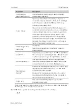
Enter domain and peer port, and select remote signaling measuring point type, remote
signaling time mark, and upload with a change.
step 5
Click configuration
to import .xml file.
step 6
Click "Save".
-- -- E
En
nd
d
9.10.11 MODBUS
Configure the MODBUforwarding service for the Logger3000 on this interface.
S
Se
errvve
err M
Mo
od
de
e
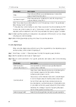
In the server mode, Logger3000 is used as a Server and connected to PC server
through Modbus TCP protocol to implement data transmission and instruction delivery.
step 1
Click "System" -> "Transfer configuration" -> "MODBUS" to enter the corresponding
interface.
step 2
For the white list setting, refer to the description in "IEC104".
-- -- E
En
nd
d
9.10.11.1 Client Mode
In the client mode, Logger3000 is used a Client and connected to PC server through
Modbus TCP protocol to implement data transmission and instruction delivery.
step 1
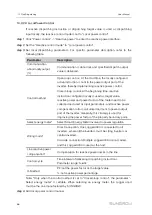
Click "System" -> "Transfer Configuration" -> "MODBUS" to enter the "Server" tab by
default.
step 2
Click "Client" to enter the corresponding tab.
step 3
Click "Add" to enter the "Advanced Settings" interface.
step 4
Enter domain and peer port and click "Save".
-- -- E
En
nd
d
9.10.11.2 RTU Mode
In the RTU mode, Logger3000 is connected to PC server through Modbus RTU protocol
to implement data transmission and instruction delivery.
step 1
Click "System" -> "Transfer Configuration" -> "MODBUS" to enter the "Server" tab by
default.
step 2
Click "RTU" to enter the corresponding tab.
step 3
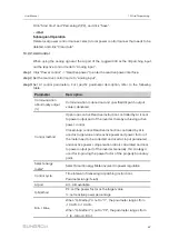
Select serial port and enter delay time.
step 4
Click
.
User Manual
Summary of Contents for Logger3000
Page 2: ......
Page 6: ......
Page 14: ...8 f fiig gu ur re e 3 3 2 2 Star networking 3 Product Introduction User Manual...


