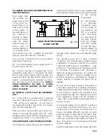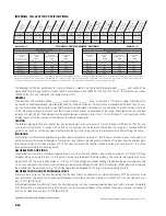
The following shall be the specifications for the solar collectors. Collectors shall be SunEarth Empire model ________, and shall be of the
glazed liquid flat plate type. Collectors shall be tested in conformance with ASHRAE 93-1986, and SRCC 100-81. The collectors also shall be
certified by the SRCC and the Florida Solar Energy Center (FSEC).
GENERAL
The dimensions of the collector shall be _________ inches in length, _________ inches in width and 3 1/4 inches in depth. The collector cas-
ing shall be an anodized aluminum extrusion (alloy 6063 T5), minimum thickness .060 inch, with an architectural dark bronze finish. The cas-
ing shall have notched framewalls for ease of plate removal and reinstallation. Sheet metal screwed fasteners shall be stainless steel (18-8
#10). The backsheet shall be painted textured aluminum not less than .014 inch thickness. A 1 inch vent plug shall be installed in each of the
four corners of the backsheet to minimize condensation.
GLAZING
The collector glazing shall be one sheet of low iron tempered glass, with a minimum of 1/8 inch thickness (5/32 inch on EP/EC 40), and
a minimum transmissivity of 91 percent (89 on EP/EC 40). The glazing shall be thermally isolated from the casing by a continuous EPDM
gasket. There shall be a continuous secondary silicone seal between the glass and casing capstrip to minimize moisture from entering the
casing.
INSULATION
The insulation shall be foil-faced polyisocyanurate foam sheathing board of a minimum 1 inch thickness, siliconed in place to the aluminum
backsheet, covered by low-binder fiberglass of a minimum 1 inch thickness, providing thermal isolation of the foam from the absorber plate.
Total thermal resistance shall be a minimum of R-12. The sides and ends of the collector shall be insulated with a minimum of 1 inch foil-faced
polyisocyanurate foam sheathing board.
ABSORBER PLATE AND PIPING
The absorber shall consist of a roll-formed copper plate of no less than .008 inch thickness. Risers shall be a minimum of 1/2 inch O.D. Type
M copper tubing on no more than 4 1/2 inch centers continuously soldered to the plate utilizing a non-corrosive solder paste with a melt-
ing point of 460
o
F. The risers shall be brazed to 1 1/8 inch O. D. Type M copper manifolds utilizing a copper phosphorous brazing alloy with
no less than 15 percent silver content, and conforming to the American Welding Society’s BCuP-5 classification. EPDM grommets shall isolate
the manifold from the aluminum casing. The absorber plate shall be designed for 160 psig maximum operating pressure.
ABSORBER COATING AND PERFORMANCE CURVE
A) Black Chrome (EC Series): The absorber coating shall be black chrome on nickel with a minimum absorptivity of 95 percent and a maxi-
mum emissivity of 12 percent. The instantaneous efficiency of the collector shall be a minimum Y-intercept of 0.714 and a slope of no less
than -0.7271 (BTU/ft
2
–hr)/F.
B) Moderately Selective Black Paint (EP Series): The absorber coating shall be a moderately-selective black paint with a minimum absorptivity
of 94 percent and a maximum emissivity of 56 percent. The instantaneous efficiency of the collector shall have a minimum Y-intercept of
0.682 and a slope of no less than -0.7995 (BTU/ft
2
–hr)/F.
Specifications subject to change without notice.
EC/EP20
EC/EP24
EC/EP32
EC/EP40
36 1/8
36 1/8
48 1/8
48 1/8
78 1/4
98 1/4
98 1/4
122 1/4
3 1/4
3 1/4
3 1/4
3 1/4
19.70
24.61
32.79
40.81
17.30
21.88
29.81
37.33
60
80
106
141
73 1/2
93 5/8
93 5/8
115 5/8
0.60
0.78
1.00
1.20
0.51
0.62
0.83
1.04
160
160
160
160
39 3/4
39 3/4
51 3/8
51 3/8
1
1
1
1
W
idth
Inches
Length Inches
D
epth
Inches
G
ross Ar
ea
Sq Ft
N
et Apertur
e
Sq Ft
D
ry
W
eight,
Lbs.
H
eader
, Center
to Center
, Inches
Fluid Capacity
U
.S. G
allons
D
esign Flow
Rate G
PM
M
axim
um
O
perating Pr
ess
PSIG
SunEarth
M
odel N
o.
Std. H
eader
W
idth, Inches
Std. H
eader
D
iam
eter
, Inches
N
om
inal
M
ax Flow
Rate G
PM
12
12
12
12
.015
.017
.018
.020
Pr
essur
e D
ro
p
at D
esign FlowRate
MODEL EP
THERMAL PERFORMANCE RATINGS*
MODEL EC
Inch-Pound Units
Category
(Ti-Ta)
CLEAR
DAY
2000
Btu/ft
2
/Day
MILDLY
CLOUDY DAY
1500
Btu/ft
2
/Day
CLOUDY
DAY
1000
Btu/ft
2
/Day
A(-9
o
F)
B
(9
o
F)
C
(36
o
F)
D
(90
o
F)
E(144
o
F)
1,284
1,169
984
619
280
971
854
677
343
62
659
542
372
89
-
Inch-Pound Units
Category
(Ti-Ta)
CLEAR
DAY
2000
Btu/ft
2
/Day
MILDLY
CLOUDY DAY
1500
Btu/ft
2
/Day
CLOUDY
DAY
1000
Btu/ft
2
/Day
A(-9
o
F)
B
(9
o
F)
C
(36
o
F)
D
(90
o
F)
E(144
o
F)
1,332
1,218
1,040
699
390
1,005
890
720
405
137
680
565
402
127
-
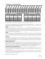
A-Pool Heating (Warm Climate) B-Pool Heating C-Water Heating (Warm Climate) D-Water Heating (Cool Climate) E-Air Conditioning/Industrial Process Heat.
Thermal performance is obtained by multiplying the collector output for the appropriate application and insolation level by the total gross collector area.
*Collector ratings are derived from the Solar Rating & Certification Corp (SRCC) Document RM-1 and Standard OG-100.
Btu
/ft
2
/Day
Ti = inlet fluid temp
Ta = ambient air temp
Btu
/ft
2
/Day
Ti = inlet fluid temp
Ta = ambient air temp
13) EMPIRE COLLECTOR SPECIFICATIONS
P.19

