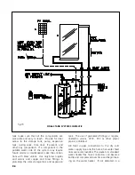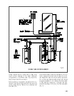
should be placed on a well insulated pad with a
minimum R-value of 10. A 2" rigid polystyrene
insulation pad such as manufactured by Frost
King (or equal) is recommended.
4.10 Electrical and Wiring Requirements
A properly licensed contractor must make the
230 volt electrical connection to the water heater
or solar storage tank and the electronic time
switch (Optional No. 32). If your solar contractor
is not allowed by law to make these connections
consult a licensed electrician.
Never activate the circuit breaker controlling
the electrical heating element until the solar
storage tank is completely filled with water.
This will prevent "dry firing" of the heating ele-
ment. The electrical heating element will be
destroyed almost instantaneously if not com-
pletely submerged in water when activated.
Make sure the water heater circuit breaker is off
until the solar storage tank is completely filled.
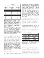
The proper gauge electrical wire to connect the
photovoltaic solar electric module and the 12 volt
DC circulating pump depends upon the distance
between the module and the pump. The electric
wire should be bare or tinned copper, two con-
ductor, PVC insulated, with a PVC UV rated gray
jacket suitable for exterior use. Table 3 defines
the minimum one way wire size for photovoltaic
powered pumps.
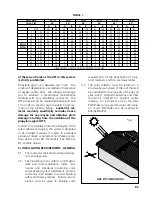
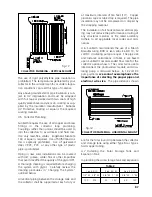
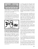
A single pole, single throw toggle switch rated
for DC amperage must be installed in series
between the photovoltaic module and the circu-
lating pump so that the pump can be turned on
and off for maintenance or during vacations.
The switch must be installed in a convenient,
unobstructed location near the top of the solar
storage tank. We recommend an Eagle 777B sin-
gle pole, single throw toggle switch mounted in
a standard UL listed box (rated at 10 amps @125
volts DC).
Connect the switch only in the positive (+) line
between the photovoltaic module and the 12
volt DC circulating pump. Wire the red leads
from the module and the pump to the two ter-
minal screws on the toggle switch. Wrap the
stripped wires 3/4 turn clockwise under the
heads of the screws without overlapping and
tighten securely. Wire the black leads (-) from the
module and pump together directly.
Wire nuts used to connect the low voltage wiring
to the photovoltaic module and circulating pump
leads shall be all plastic, sealed with silicone and
thoroughly wrapped with electrician’s tape.
The photovoltaic solar electric module shall be
the Siemens SM20 or equal. The photovoltaic
module shall have a nominal power rating of 20
watts at 14.5volts/1.38 amps.
4.11 Charging the System
Once the components are plumbed you are ready
to fill the solar storage tank with water and to
charge the collector loop with a mixture of heat
transfer fluid (HTF) and distilled or deionized
water. The use of regular tap water as a mixing
agent is prohibited.
Proceed as follows:
4.11.1 Begin by filling the solar tank with water.
Do this by opening the cold water isolation ball
valve to the solar tank (No. 22). When the tank
is filled, inspect all threaded fittings and solder
joints for leaks.
4.11.2 Fill and pressurize the solar collector loop
with water. Begin by connecting a washing
machine hose to the upper charge valve (No. 9)
and fill the collector loop with water. The isola-
tion ball valve (No. 10) remains closed at this
point. While the hose is still connected to the
P.11
Table 3
Minimum Conductor Size - One Way
Photovoltaic Module Output – Nominal 20 Watts
18 AWG
16 AWG
14 AWG
12 AWG
10 AWG
8 AWG
N/A 26
ft
52ft
78ft
130ft
208ft
fig.17
ELECTRICAL COMPONENTS


