


Page 44
SENSORS
800 LCD P
ANEL
240
V
A
C,
32A / 40A / 48A
1 PHASE,
60 Hz;
USE MIN.
6 A
WG
COPPER CONDUCT
ORS ONL
Y
J4
J8
J2
K8
K6
K5
K4
K1
K2
K3
K7
J1
Z1
J6
J7
J3
OPTIONS
FLO
W SWITCH
HI - LIMIT / FREEZE SENSOR
Maxxus
Control P
a
nel
TRANSFORMER
T1
RED
Red
Wht
Wht
Wht
Blk
Blk
Blk
Red
Red
Blk
BLK
Blk
20A, 250V
MD
A20
F2
PUMP 3
PUMP 1
T92
Rela
y
HI
Wht
Wht
Blk
Blk
PUMP 2
HI
HI
LO
TB3
TB2
TB6
TB1
TB1
GRN
11
1
B
B
Y
Y
3
5
6
8
10
1
2
1
2
JP20
JP19
JP9
1
1 3 5 7 9
1 3 5 7 9
11 13
TEMPERA
TURE
SENSOR
To
Heater &
Pump 2 Rela
y
F
rom
TB1
SP
A LIGHT
TB5
TB3
F
rom TB1
K13
30A,
250V
SC-30
F1
UV or CD
Oz
onator
(Optional)
INTERLOCK
JUMPER
HEA
TER
5.5 kW
, 240
V
A
C
Circulation
Pump
Pe
rimeter
Light Module
A
utomatic
(Photocell)
Pe
rmimeter
Lights
STEREO
(Optional)
This de
vice complies with par
t 15 of
the FCC r
ules
. Oper
ation is subject to
the f
ollo
wing tw
o conditions:
1.
This de
vice ma
y not cause har
mful
interf
erence
.
2.
This de
vice m
ust accept an
y
interf
erence receiv
ed including
interf
erence that ma
y cause
undesired oper
ation.
Po
w
er Supply
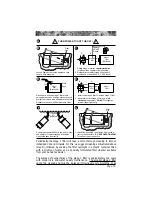
15.0 Electrical Wiring Diagram
(Domestic, 240 VAC/60 Hz)


