7.
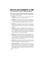
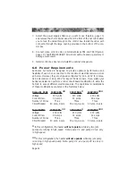
Select the power supply entrance you want to use (Figure-A, page 10)
and remove the short cabinet panel from the front of the hot tub to allow
you to feed the cable through to the control box. Install the cable with
connector through the large opening provided in the bottom of the con-
trol box.
8.
Connect wires, color to color, on terminal blocks TB1 and TB3 (Figure-C,
page 10). TIGHTEN SECURELY! All wires must be hooked up securely or
damage could result.
9.
Install control box door and reinstall the cabinet side panels.
6.0 Power Requirements
Sundance hot tubs are designed to provide optimum performance and
flexibility of use when connected to the maximum electrical service as list-
ed below. However, they are shipped configured for 60A, 240V for domes-
tic 60Hz models or 45A, 230V for Export 50Hz models. If you prefer, your
Sundance dealer can perform a minor circuit board modification to allow the
hot tub to accept different electrical service. The operational considerations
of these modifications are listed in the footnotes below.
Domestic 60Hz
240V/40A
**
240V/50A
*
240V/60A
***
Voltage
240 volts
240 volts
240 volts
Current Draw
32 amps
40 amps
48 amps
Number of Wires
Three
Three
Three
Circuit Breaker
40 amp, 2-pole
50 amp, 2-pole
60 amp, 2-pole
Export 50Hz
230V/40A
**
230V/45A
*
230V/50A
***
Voltage
230 volts
230 volts
230 volts
Current Draw
26 amps
34 amps
42 amps
Number of Wires
Three
Three
Three
Circuit Breaker
40 amp, 2-pole
45 amp, 2-pole
50 amp, 2-pole
*
In this configuration, the heater
will not operate
while any two jets
pumps are running in high speed.
Note: pump #2 and pump #3 run only
in high speed.
**
In this configuration, the heater
will not operate
while any jets pump
is running in high speed pump.
Note: pump #2 and pump #3 run only in
high speed.
Page 12


