background image

2-2

Sun Ultra 80 SCSI Cable Installation Guide • March 2000

Note –

If the system will not shut down, such as when the operating system has

crashed, press and hold the power switch for at least five seconds.

4. Verify the following:

a. The front panel LED is off.

b. The system fans are not spinning.

Caution –

Disconnect the power cord prior to servicing system components.

5. Turn off the power to the monitor.

6. Disconnect cables to any peripheral equipment.

7. Remove the lock block, if installed (

FIGURE 2-2

).

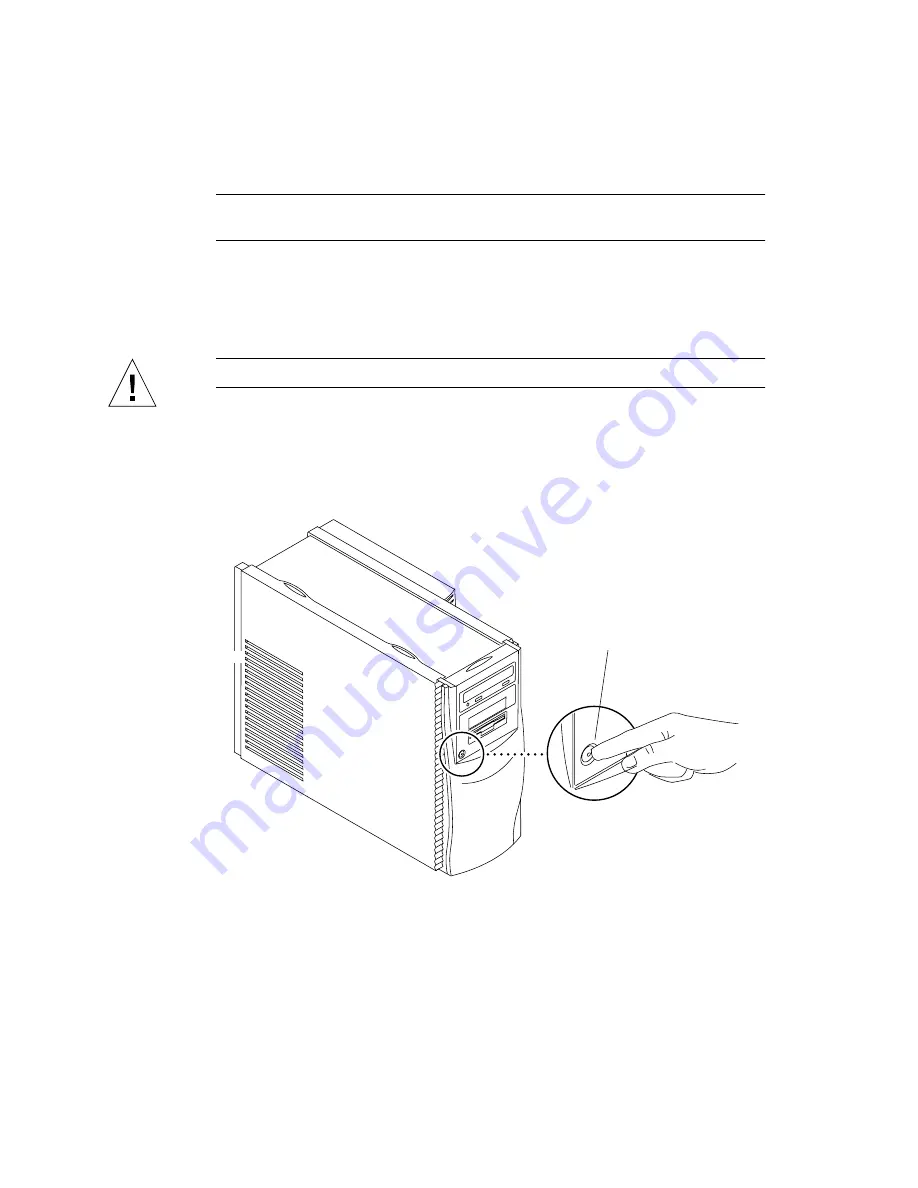
FIGURE 2-1

System Power

Power switch

Summary of Contents for Ultra 80 SCSI

Page 1: ...ystems Inc 901 San Antonio Road Palo Alto CA 94303 U S A 650 960 1300 Send comments about this document to docfeedback sun com Sun Ultra 80 SCSI Cable Installation Guide Part No 806 4423 10 March 2000 Revision A ...

Page 2: ...Sun Microsystems Inc 901 San Antonio Road Palo Alto CA 94303 4900 Etats Unis Tous droits réservés Ce produit ou document est protégé par un copyright et distribué avec des licences qui en restreignent l utilisation la copie la distribution et la décompilation Aucune partie de ce produit ou document ne peut être reproduite sous aucune forme par quelque moyen que ce soit sans l autorisation préalabl...

Page 3: ...t Related Documentation Accessing Sun Documentation Online The docs sun comsm web site enables you to access Sun technical documentation on the Web You can browse the docs sun com archive or search for a specific book title or subject at http docs sun com Application Title Part Number Service Sun Ultra 80 Service Manual 805 6618 ...

Page 4: ...r a list of documents and how to order them visit the Sun Documentation Center on Fatbrain com at http www1 fatbrain com documentation sun Sun Welcomes Your Comments Sun is interested in improving its documentation and welcomes your comments and suggestions You can email your comments to Sun at docfeedback sun com Please include the part number of your document in the subject line of your email ...

Page 5: ...and Internal Access 2 1 2 1 Powering Off the System Removing the Access Panel 2 1 2 2 Attaching the Antistatic Wrist Strap 2 5 2 3 Replacing the Access Panel Powering On the System 2 6 3 Removing and Replacing the Peripheral Assembly 3 1 3 1 Removing the Peripheral Assembly 3 1 3 2 Installing an Optional Component 3 3 3 3 Replacing the Peripheral Assembly 3 4 4 Installing the Optional SCSI Cable C...

Page 6: ...vi Sun Ultra 80 SCSI Cable Installation Guide March 2000 ...

Page 7: ...mbly removable media drive bay This book explains how to install the optional SCSI cable component when a second SCSI removable media drive is added to the system For more detail on the Sun Ultra 80 system please consult the Sun Ultra 80 Service Manual part number 805 6618 FIGURE 1 1 Ultra 80 Workstation Peripheral assembly removable media drive bay ...

Page 8: ... device with a 50 pin connector to be installed in the peripheral assembly removable media drive bay The device may be a 4 mm tape drive an 8 mm tape drive or a second CD ROM drive 1 3 SCD Compliance Sun Ultra 80 systems have been independently tested and verified to comply with revision 2 1 of the SPARC Compliance Definition SCD developed by SPARC International Inc These systems are binary compat...

Page 9: ...ASP or advanced computer system end user who has experience troubleshooting and replacing hardware you may want to start with Chapter 4 Installing the Optional SCSI Cable Component Otherwise first read and perform the procedures in sequence in Chapter 2 Powering On Off and Internal Access and Chapter 3 Removing and Replacing the Peripheral Assembly ...

Page 10: ...1 4 Sun Ultra 80 SCSI Cable Installation Guide March 2000 ...

Page 11: ...n page 2 6 2 1 Powering Off the System Removing the Access Panel To power off the system and remove the access panel Caution Prior to turning off the system power exit from the operating system Failure to do so may result in data loss 1 Back up system files and data 2 Halt the system Caution Pressing the power switch does not remove all power from the system a trickle voltage remains in the power ...

Page 12: ...ower switch for at least five seconds 4 Verify the following a The front panel LED is off b The system fans are not spinning Caution Disconnect the power cord prior to servicing system components 5 Turn off the power to the monitor 6 Disconnect cables to any peripheral equipment 7 Remove the lock block if installed FIGURE 2 2 FIGURE 2 1 System Power Power switch ...

Page 13: ...rlock circuit This safety mechanism prevents all DC voltages except 5 VDC standby power from reaching any internal components when the access panel is removed a Lay the system in the service position b Press down on the two depressions at the top of the access panel Tilt the top of the access panel out about an inch c Lift the access panel up and clear of the chassis Lock block Workstation ...

Page 14: ...2 4 Sun Ultra 80 SCSI Cable Installation Guide March 2000 FIGURE 2 3 Removing Replacing the Access Panel Access panel Depression 2 ...

Page 15: ...d then disconnect the power cord from the system and the wall receptacle Following this caution equalizes all electrical potentials with the system 1 Disconnect the power cord 2 Attach the antistatic wrist strap as follows FIGURE 2 4 a Unwrap the first two folds of the antistatic wrist strap and wrap the adhesive side firmly against your wrist b Peel the liner from the copper foil at the opposite ...

Page 16: ...el and power on the system as follows FIGURE 2 3 Caution If the access panel is installed incorrectly the power interlock circuit will remain activated Ensure that the access panel is installed correctly 1 Hold the access panel centering it over the chassis opening 2 Lower the access panel lightly onto the chassis until the access panel hooks engage the chassis rail Chassis Antistatic wrist strap ...

Page 17: ...r cord to the wall and the system 9 Momentarily press the power switch FIGURE 2 1 or the Type 6 keyboard power key FIGURE 2 5 10 Verify the following a The front panel LED is on b The system fans are spinning FIGURE 2 5 Type 6 Keyboard Help Stop Again Props Front Open Find Cut Paste Copy Undo Esc F2 F1 F3 F4 F5 F6 F7 F8 1 2 3 4 5 6 7 8 9 0 _ Back Space F9 F10 F11 F12 Tab Q W E R T Y U I O P Caps L...

Page 18: ...2 8 Sun Ultra 80 SCSI Cable Installation Guide March 2000 ...

Page 19: ... off the system and remove the access panel See Section 2 1 Powering Off the System Removing the Access Panel on page 2 1 Caution Use proper ESD grounding techniques when handling components Wear an antistatic wrist strap and use an ESD protected mat Store ESD sensitive components in antistatic bags before placing them on any surface 3 Attach the antistatic wrist strap See Section 2 2 Attaching th...

Page 20: ...Partially remove the peripheral assembly from the chassis d Disconnect the power and interface cables from all drives installed in the peripheral assembly e Remove the peripheral assembly from the chassis 5 Place the peripheral assembly on an antistatic mat FIGURE 3 1 Removing and Replacing the Peripheral Assembly Screw 4 Peripheral assembly Peripheral bezel assembly ...

Page 21: ... Use proper ESD grounding techniques when handling components Wear an antistatic wrist strap and use an ESD protected mat Store ESD sensitive components in antistatic bags before placing them on any surface 1 Remove the filler panel if necessary FIGURE 3 2 2 Position the optional component into the middle shelf of the peripheral assembly 3 Using a No 2 Phillips screwdriver tighten the four screws ...

Page 22: ...e 1 Replace the peripheral assembly as follows FIGURE 3 2 a Position the peripheral assembly into the chassis b Connect the rear cable connectors as required c If an optional drive component is being installed undress the optional drive component power harness and route it from the CPU area into the peripheral area d Using a No 2 Phillips screwdriver tighten the captive screws securing the periphe...

Page 23: ...moving and Replacing the Peripheral Assembly 3 5 3 Detach the antistatic wrist strap 4 Replace the access panel and power on the system See Section 2 3 Replacing the Access Panel Powering On the System on page 2 6 ...

Page 24: ...3 6 Sun Ultra 80 SCSI Cable Installation Guide March 2000 ...

Page 25: ...able from the SCSI terminator board and from the existing SCSI device b Remove the old SCSI cable from the system c Connect the male end of the optional SCSI cable connector to the female end of the SCSI terminator board d Install the SCSI cable onto the cable management hooks part of chassis e Connect the middle connector of the new SCSI cable onto the rear connector of the peripheral assembly to...

Page 26: ...Ultra 80 SCSI Cable Installation Guide March 2000 FIGURE 4 1 Installing the Optional SCSI Cable Component SCSI terminator board Optional SCSI cable component SCSI cable end connector SCSI cable middle connector ...

Page 27: ...Chapter 4 Installing the Optional SCSI Cable Component 4 3 FIGURE 4 2 Reinstalling the Power Cables Power connector 2 ...

Page 28: ...4 4 Sun Ultra 80 SCSI Cable Installation Guide March 2000 ...

Reviews: