8-18
Sun Ultra 1 Series Service Manual—November 1995
8
.
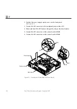
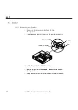
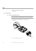
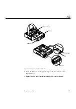
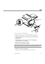
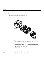
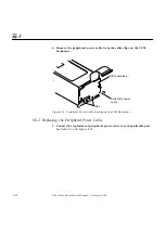
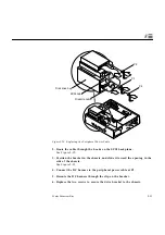
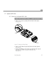
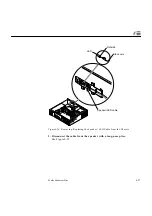
Figure 8-15 Removing the SCSI Backplane
9. Remove the SCSI backplane from the bracket.
See Figure 8-15.
8.5.2 Replacing the SCSI Cable/Backplane
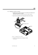
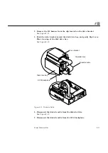
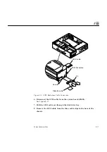
1. Route the SCSI cable under the three cable clips in the base of the chassis
and through the opening near the front edge of the system board.
See Figure 8-15.
2. Connect the SCSI cable to the system board at J2602.
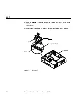
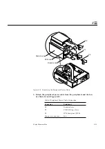
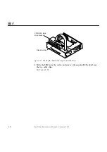
3. Position the SCSI backplane on the disk drive bay so the SCSI backplane
slots sit on the tabs.
See Figure 8-16.
SCSI
backplane
SCSI cable
J2602
Cable clips
Disk drive bay
Summary of Contents for Ultra 1 140
Page 6: ......
Page 8: ...Sun Ultra 1 Series Service Manual November 1995...
Page 12: ...x Sun Ultra 1 Series Service Manual November 1995 Glossary Glossary 1 Index Index 1...
Page 23: ...Part1 SystemInformation Product Description page 1 1...
Page 24: ......
Page 28: ...1 4 Sun Ultra 1 Series Service Manual November 1995 1...
Page 30: ......
Page 46: ...3 14 Sun Ultra 1 Series Service Manual November 1995 3...
Page 62: ...4 16 Sun Ultra 1 Series Service Manual November 1995 4...
Page 63: ...Part3 PreparingforService Safety and Tool Requirements page 5 1 Power On and Off page 6 1...
Page 64: ......
Page 68: ...5 4 Electron Service Manual November 1995 5...
Page 72: ......
Page 108: ...8 32 Sun Ultra 1 Series Service Manual November 1995 8...
Page 121: ...Part5 SystemBoard System Board and Component Replacement page 10 1...
Page 122: ......
Page 147: ...Part6 IllustratedPartsBreakdown Replacement Parts page 11 1...
Page 148: ......
Page 152: ......
Page 166: ...C 4 Sun Ultra 1 Series Service Manual November 1995 C...
Page 170: ...Glossary 4 Sun Ultra 1 Series Service Manual November 1995...
Page 174: ...Index 4 Sun Ultra 1 Series Service Manual November 1995...

